
Summary
A VoluMill repositioning move can appear to travel through the part when a 2D operation is calculated from mixed Wall and Air Wall geometry without the applicable solid body selected. An Air Wall tells VoluMill that the stock ends at that boundary; after the tool crosses it, the calculation continues to regard the area as air until another boundary changes that state.
Because wireframe boundaries do not describe the rest of the three-dimensional part, the reliable correction is to include the appropriate solid body in the VoluMill operation. The solid supplies the missing part information so VoluMill can recognize and avoid it. Recalculate the operation, inspect every high-feed repositioning move, and complete simulation and posted-code review before machining.
Table of Contents
- Before You Begin
- Why the Repositioning Move Crosses the Part
- Procedure
- Best Practices
- Troubleshooting
- Related Articles
Before You Begin
Open the GibbsCAM file and identify the VoluMill operation whose repositioning move crosses the part.
Save a backup copy before changing selected inputs, Wall or Air Wall designations, or process settings.
Confirm that the correct solid part body exists, is valid, and is positioned in the same machining coordinate system as the selected geometry.
Identify which segments are intended to retain material as Walls and which segments are true open sides that should be Air Walls.
Review the operation's Floor Clearance and High Feedrate values, but do not treat either value as a substitute for complete part geometry.
Plan to inspect Op Simulation and the posted program using the shop's normal verification and prove-out procedures.
Important: A repositioning move is not safe merely because it is displayed as a non-cutting or high-feed move. If the operation lacks the solid body that represents nearby material, the toolpath calculation may not know that material exists.
Why the Repositioning Move Crosses the Part
VoluMill often moves from the end of one cut to the beginning of the next through an area it considers already machined. These in-process repositioning moves use the programmed High Feedrate and can remain near the pocket floor according to the Floor Clearance value.
With geometry-only input, VoluMill knows the selected chains and their Wall or Air Wall behavior, but it does not automatically know the complete shape of material outside those chains. Mixed Wall/Air Wall definitions are especially sensitive because crossing an Air Wall places the tool in a region treated as air until another boundary is crossed. A solid body provides the missing three-dimensional part definition.
Procedure
Step 1 - Confirm the Operation Is Using Geometry Only
Open the affected VoluMill process and review the items selected for machining.
Determine whether the selection contains only wireframe geometry or profiler-created shapes and does not include the applicable solid body.
Inspect the generated toolpath and identify the exact repositioning segment that crosses the part.
Note which Air Wall the tool crosses before entering the region that VoluMill treats as air.
Expected Result
The unsafe-looking move is traced to a geometry-only mixed Wall/Air Wall definition, or another missing-input condition is identified for correction.
Step 2 - Validate the Wall and Air Wall Definition
Verify that every segment intended to retain material is designated as a Wall.
Use Air Walls only at actual open sides of the pocket where the stock ends and the tool may enter or exit.
Check that the geometry is connected as intended and that no segment was accidentally assigned the wrong feature type.
Follow the boundary from the repositioning move's point of view and identify where the calculation enters air and where it next crosses a boundary.
Expected Result
The open-pocket geometry accurately distinguishes material-retaining Walls from true Air Wall openings.
Step 3 - Include the Solid Body in the VoluMill Operation
Display and select the solid body that represents the part material VoluMill must recognize.
Keep the required 2D Wall/Air Wall geometry selected when it is needed to define the open-sided pocket, and add the applicable solid body to the operation input.
Confirm that the selected body is the correct revision, is located correctly, and belongs to the active part setup.
If the Solids tab is available, review its containment, stock, and avoidance-related settings for the intended operation.
Expected Result
The operation contains both the boundary information needed for the open pocket and the solid model needed to recognize the surrounding part.
Step 4 - Recalculate and Inspect the Toolpath
Generate or recalculate the VoluMill operation after changing the selected input.
Inspect the full toolpath, paying particular attention to High Feedrate moves between cuts.
Confirm that the former crossing move now routes around or above the solid rather than through it.
Review entry moves, exits, links, islands, pocket walls, depths, and stock allowance for unintended changes caused by the new input.
Expected Result
The recalculated toolpath recognizes the solid part and no longer uses the previously assumed air region as an unobstructed repositioning route.
Step 5 - Review the Repositioning Parameters
Set Plunge Clearance to the shop-approved distance at which Rapid motion ends above the part and feed motion begins.
Use a positive Floor Clearance when repositioning moves should lift above the already-machined floor; a value of zero allows the tool to drag across that floor.
Set High Feedrate to a safe, machine-appropriate non-Rapid feedrate for interpolated linear and circular repositioning moves.
Do not use a larger Floor Clearance or a slower High Feedrate to conceal an incorrect part definition. Correct the selected geometry and solid input first.
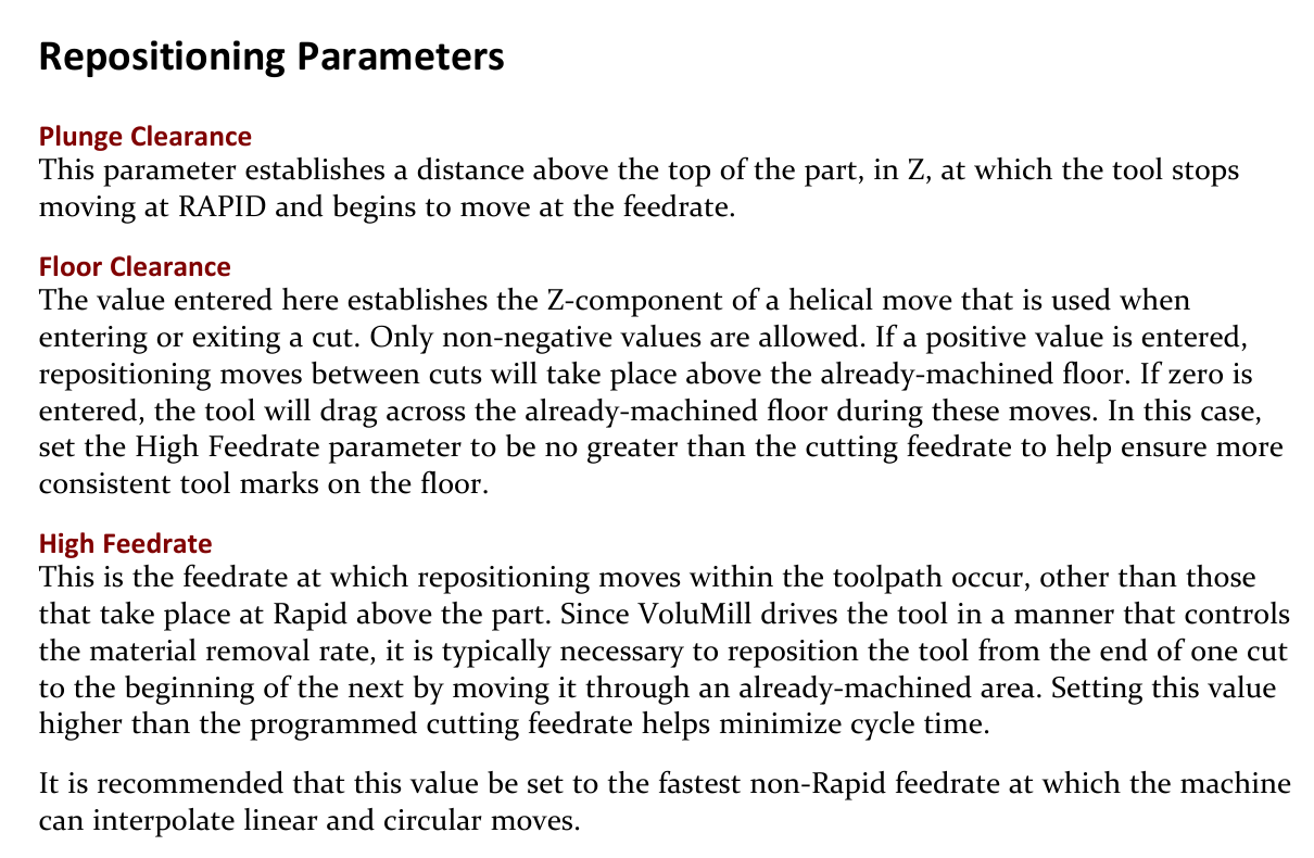
Figure 1 - VoluMill Repositioning Parameters in the GibbsCAM 2026 documentation.
Expected Result
Repositioning parameters are appropriate for the machine and operation after the toolpath has been calculated from complete part information.
Step 6 - Simulate and Verify the Complete Operation
Run Op Simulation with the part, stock, tool, and holder visible and collision checking enabled where available.
Slow or stop the simulation around each entry, exit, and repositioning move that approaches the part.
Rotate the view and verify tool and holder clearance from the part, stock, fixtures, and other modeled components.
Review the posted program for the same repositioning move, feedrate, clearance, and operation order shown in GibbsCAM.
Resolve every discrepancy and follow the shop's prove-out procedure before releasing the program to the machine.
Expected Result
The complete operation has no repositioning move through modeled part material, and the posted program agrees with the verified toolpath.
Expected Result
The VoluMill operation retains the intended open-sided Wall/Air Wall pocket definition while also using the applicable solid body as part information. High-feed repositioning moves remain in known clear or already-machined regions, and the operation passes toolpath inspection, simulation, posted-code review, and shop prove-out.
Best Practices
Select the applicable solid body whenever geometry-only Wall/Air Wall input cannot fully describe surrounding material.
Use Air Walls only where the stock actually ends; use Walls wherever material must remain protected.
Treat Floor Clearance and High Feedrate as motion controls, not as part-definition or collision-avoidance controls.
After changing selected bodies or feature types, regenerate the operation before judging the result.
Inspect all repositioning moves, not only cutting moves, from more than one view.
Keep the solid model, geometry, stock, and machining coordinate system aligned and current.
Enable tool and holder collision checking during final simulation when the installed options support it.
Review the posted program because post-processor logic can change feeds, motion types, or output details.
Retain a backup file and document why the solid was added so future edits do not return the operation to geometry-only calculation.
Troubleshooting
Problem: The High Feedrate repositioning move still passes through the part.
Possible Causes
The solid body was visible but not selected as an operation input.
The wrong body or an outdated body revision was selected.
The operation was not regenerated after the selection changed.
The solid is invalid, mispositioned, or not part of the active setup.
Resolution
Edit the operation, explicitly select the correct solid together with the required Wall/Air Wall geometry, confirm its position, and regenerate the operation. Inspect the new repositioning path before simulation.
Problem: Increasing Floor Clearance does not stop the move from crossing the part.
Possible Causes
Floor Clearance changes the Z component of moves over an area VoluMill already considers machined.
The calculation still lacks the solid or boundary information that identifies the obstructing material.
Resolution
Restore the missing part definition by selecting the applicable solid body and correcting any Wall/Air Wall designations. Then recalculate the toolpath and set Floor Clearance according to the machining requirement.
Problem: The pocket opening behaves like a solid wall, or the tool will not use the open side.
Possible Causes
The opening was designated as a Wall instead of an Air Wall.
The mixed-shape geometry is disconnected, reversed, or selected in an unintended order.
The solid or containment settings close the intended access region.
Resolution
Correct the feature types and geometry connectivity, confirm the intended open side, review the solid-related containment settings, and regenerate the operation.
Problem: The operation changes significantly after the solid body is added.
Possible Causes
The solid exposes material or boundaries that were absent from the geometry-only calculation.
The solid position, depths, stock allowance, containment, or selected faces do not match the intended pocket.
A different body revision was selected.
Resolution
Verify the body revision and position, then review depths, stock, containment, Walls, Air Walls, islands, and entry settings. Regenerate and compare the entire toolpath rather than accepting only the corrected repositioning segment.
Problem: Simulation does not report a collision even though the move appears to enter material.
Possible Causes
Collision checking or its feedback options are disabled.
The part, stock, tool holder, or required body is hidden or absent from simulation.
The selected simulation mode does not check the required components.
Resolution
Use Op or Machine Simulation as appropriate, display all required bodies and tooling, enable collision checking and stop or log feedback, and rerun the full operation. Do not release the program based only on an unverified display.
Problem: No toolpath is generated after the solid is selected.
Possible Causes
The selected body and Wall/Air Wall geometry do not define a valid machining region.
Depth, containment, stock, or tool-size settings leave no machinable material.
The body contains invalid or damaged solid geometry.
Resolution
Confirm the machining region, selected inputs, depths, containment, stock allowance, and tool size. Repair or replace an invalid body, then regenerate and inspect any messages reported by the process.
Additional Information
The VoluMill documentation states that 2D geometry and 3D bodies can be used as machining inputs. Geometry supports open-sided pockets through Air/Wall features, while selected solids, sheets, or facet bodies provide three-dimensional information to the process.
VoluMill's repositioning controls assume the move occurs through an area the calculation considers clear or already machined. A positive Floor Clearance raises the move above the floor, and High Feedrate controls the non-Rapid interpolation speed; neither setting reconstructs missing part material outside the selected wireframe boundary.
Related Articles
- Recommended Simulation Settings
- How to Set Fixture Avoidance
- Extracting Geometry from Solids
- Solid Model Looks Distorted
Explore More from CAMCO
Visit the CAMCO website to learn more about:
Keywords
GibbsCAM, VoluMill, Air Wall, Air Walls, Wall Features, Mixed Shape, Open Pocket, Open-Sided Pocket, Repositioning, Repositioning Move, High Feedrate, Floor Clearance, Plunge Clearance, Geometry Only, Solid Body, Solid Selection, Toolpath Through Part, Collision Checking, Op Simulation, Toolpath Verification