
Summary
VoluMill can ignore a small Air Wall opening or void when calculating a Helix entry. Small empty regions are intentionally filtered when continuing through them is more efficient than interrupting the normal machining pattern. The same filtering applies to entry selection, so an opening that appears usable may not be large enough for VoluMill's calculated helix and first cutting pass.
As a practical starting point, make the available opening approximately 2 x Tool Diameter + Stepover + 2 x Tolerance. This gives VoluMill space comparable to the envelope it would create with a helical entry and avoids forcing an excessively tight first pass. Treat the result as a rule of thumb, regenerate the operation, and verify the actual helix, first engagement, simulation, and posted program.
Table of Contents
- Before You Begin
- Why a Small Air Wall or Void Is Ignored
- Rule-of-Thumb Opening Size
- Procedure
- Best Practices
- Troubleshooting
- Related Articles
Before You Begin
Open the GibbsCAM file and save a backup copy before changing Air Wall geometry, tool data, tolerance, stepover, or plunge controls.
Confirm that the affected operation uses VoluMill and that Plunge Type is set to Helix.
Identify the Air Wall opening or void where the helix is expected to begin and measure its usable clear width at the entry region.
Record the actual tool diameter, programmed stepover, and process tolerance in the same units.
Verify that the selected geometry, stock, islands, solids, depths, coordinate system, tool, and holder represent the intended setup.
Keep the original operation available for comparison so the effect of each change can be isolated.
Plan to inspect the complete entry and first cutting pass in simulation and in the posted program before machining.
Important: The clearance expression in this article is a practical sizing guideline, not a guaranteed internal threshold. The final entry also depends on the selected region, toolpath parameters, nearby material, and the entry candidates VoluMill can calculate.
Why a Small Air Wall or Void Is Ignored
When a small void appears along an otherwise efficient cutting path, VoluMill may treat the region as too small to justify interrupting the cut. This helps prevent unnecessary motion through minor gaps. When the desired entry lies in that same region, the filtered void is not available as a meaningful entry area.
A Helix entry needs more than the tool diameter alone. VoluMill must fit the rotating tool-center path and leave enough room for the first cutting pass. If the opening is only slightly larger than the cutter, the initial engagement can be too tight, so VoluMill may choose another entry location or ignore the void.
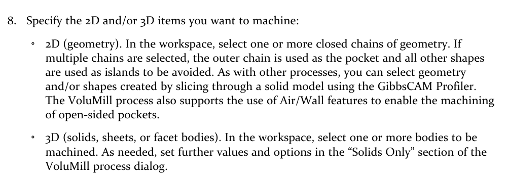
Figure 1 - The VoluMill documentation identifies Air/Wall features as a method for machining open-sided pockets.
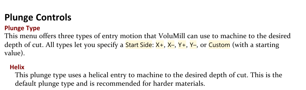
Figure 2 - Helix is a VoluMill plunge type that uses helical motion to reach the desired depth.
Rule-of-Thumb Opening Size
Approximate minimum clear opening = 2 x Tool Diameter + Stepover + 2 x Tolerance
Example: For a 0.500 in tool, 0.050 in stepover, and 0.001 in tolerance, the starting estimate is 2(0.500) + 0.050 + 2(0.001) = 1.052 in. The same calculation works in metric when every input uses millimeters.
Procedure
Step 1 - Confirm the Entry Behavior
Open the affected VoluMill process and confirm that Plunge Type is Helix.
Generate the operation without changing any settings and identify the actual helix location.
Inspect the intended Air Wall opening or void and confirm that it belongs to the selected machining definition.
Measure the smallest usable clear width at the entry region, accounting for nearby Walls, islands, uncut material, and solid boundaries.
Expected Result
A baseline operation and the true usable opening are available for comparison.
Step 2 - Calculate a Starting Opening Size
Record Tool Diameter (D), Stepover (S), and Tolerance (T) using one unit system.
Calculate the starting target with O = 2D + S + 2T.
Compare the calculated value with the smallest usable width of the intended opening.
If the measured opening is below the estimate, expect VoluMill to ignore it or select a different entry unless the machining strategy is changed.
Expected Result
The opening is classified as likely adequate or undersized for the current toolpath inputs.
Step 3 - Correct the Entry Condition
When permitted by the part and stock definition, enlarge the Air Wall opening or void so its usable width meets or exceeds the starting estimate.
If the opening cannot change, evaluate a smaller tool or a smaller stepover that remains appropriate for the material, tool, and machining objective.
Use a different approved entry strategy when the required Helix envelope cannot fit safely.
Do not reduce tolerance merely to force the entry; maintain the accuracy required by the part and shop standard.
Expected Result
The process inputs provide a realistic helix envelope without compromising required accuracy or machining safety.
Step 4 - Regenerate and Inspect the First Pass
Regenerate the VoluMill operation after each geometry, tool, stepover, tolerance, or plunge-control change.
Confirm whether the helix now begins in the intended Air Wall opening or void.
Inspect the full helical motion, tool-center radius, initial engagement, first cutting pass, and transition into the main toolpath.
If the entry remains elsewhere, remeasure the usable opening and review all nearby material and selected boundaries before making another controlled change.
Expected Result
The generated entry uses the intended opening when it is a valid candidate, and the first pass has adequate room.
Step 5 - Simulate, Post, and Prove Out
Run Op Simulation and review the entry at a slow playback rate from multiple views.
Check the cutter, shank, and holder against stock, the part, fixtures, islands, and nearby walls throughout the helix and first pass.
Verify plunge feeds, spindle speed, depths, clearances, and the transition from entry motion to cutting motion.
Post the complete operation sequence and confirm that the output matches the simulated entry and the machine/control requirements.
Follow the shop's approved single-block, dry-run, and prove-out procedure before production machining.
Expected Result
The intended entry is verified in both simulation and posted code, with safe clearance and acceptable first-pass engagement.
Expected Result
When the Air Wall opening or void is large enough for the current cutter, stepover, tolerance, and surrounding geometry, VoluMill can use it as a Helix entry candidate. The resulting helix and first cutting pass have adequate room rather than being forced through an undersized gap. If the opening is still filtered or is not otherwise a valid candidate, VoluMill selects another entry and the machining strategy must be revised instead of forcing the location.
Best Practices
Treat 2D + S + 2T as a starting estimate and confirm the generated result; do not treat it as an exact guaranteed threshold.
Measure the smallest usable opening at the actual entry region, not only the largest visible distance between endpoints.
Keep Tool Diameter, Stepover, Tolerance, and opening measurements in the same units.
Change one input at a time and regenerate so the cause of the toolpath change remains clear.
Do not lower tolerance below the part or shop requirement to obtain a preferred entry.
Review the first cutting pass as carefully as the helix because adequate tool clearance alone does not guarantee acceptable engagement.
Include applicable solid and stock information when geometry alone does not describe nearby material.
Recheck the opening whenever the tool, stepover, tolerance, stock, geometry, or depth changes.
Verify the posted program and use the shop's complete prove-out process before machining.
Troubleshooting
Problem: VoluMill does not place the Helix entry in the Air Wall opening or void.
Possible Causes
The usable opening is smaller than the envelope required by the tool, stepover, and tolerance.
The void is filtered as a minor region during normal VoluMill calculation.
The intended opening is not part of the selected machining definition or is restricted by nearby material.
Resolution
Measure the smallest usable width and compare it with O = 2D + S + 2T. Correct the geometry or machining strategy, regenerate, and confirm the new entry instead of assuming the visible gap is sufficient.
Problem: The entry works with a smaller tool but not with the production tool.
Possible Causes
Tool Diameter contributes twice to the estimated opening requirement.
The larger tool also changes the available helix radius and first-pass engagement.
The production tool or holder has less clearance near the opening.
Resolution
Recalculate the opening with the production tool's actual diameter and verify holder clearance. Enlarge the valid opening, reduce stepover when appropriate, or select another approved tool or entry strategy.
Problem: The void looks wide enough on screen but is still ignored.
Possible Causes
The narrowest part of the opening is smaller than the displayed maximum width.
Tolerance, nearby Walls, islands, stock, or solids reduce the usable region.
The opening does not remain clear through the required entry depth.
Resolution
Measure the complete usable entry region at the relevant depth and inspect all selected boundaries and bodies. Correct missing or conflicting inputs, regenerate, and review the full helix rather than relying on the screen view alone.
Problem: Reducing tolerance does not move the Helix entry into the void.
Possible Causes
Tolerance is only one term in the estimate and may be small relative to twice the tool diameter.
The opening remains below the practical size needed for the helix and first pass.
Another entry location remains more suitable for the calculated toolpath.
Resolution
Restore the accuracy required by the part, then address the dominant condition: opening size, tool diameter, stepover, selected geometry, or entry strategy. Do not sacrifice tolerance simply to influence entry selection.
Problem: The helix appears to fit, but the first cutting pass is too tight.
Possible Causes
The opening was evaluated only against the cutter diameter, not the complete helix and stepover envelope.
The programmed stepover creates excessive initial radial engagement.
Nearby material or an island reduces the available first-pass clearance.
Resolution
Increase the usable opening or revise the tool, stepover, or entry strategy. Regenerate and inspect both the rotating helix and the first complete cutting pass before accepting the operation.
Problem: A previously acceptable Helix entry changes after the operation is edited.
Possible Causes
Tool Diameter, Stepover, Tolerance, geometry, stock, depth, or selected bodies changed.
The edit changed which voids are filtered or which entry candidates are valid.
The operation was regenerated with a different active coordinate system or setup.
Resolution
Recalculate the starting opening size from the current inputs, confirm the selected geometry and setup, regenerate, and repeat simulation and posted-code review. Do not rely on the earlier entry after a toolpath-affecting change.
Additional Information
Scope of the guideline: The expression estimates the clear opening needed for a practical Helix entry and first pass. It does not force a particular entry point, guarantee that a void will become a candidate, or replace tool-manufacturer limits, collision checking, simulation, posted-code review, or machine prove-out.
Related Articles
- How to Machine Pockets from Outside In
- Feed Rate Calculation
- Recommended Simulation Settings
- How to Set Fixture Avoidance
Explore More from CAMCO
Visit the CAMCO website to learn more about:
Keywords
GibbsCAM, VoluMill, Helix Entry, Air Wall, Airwall, Void, Plunge Controls, Plunge Type, Tool Diameter, Stepover, Tolerance, Helix Clearance, Entry Point, Open Pocket, First Pass, VoluMill Entry