Summary
GibbsCAM 2026 improves material calculation for multi-sided, nonconvex turning tools such as CoroTurn Prime inserts. The updated calculation uses more of the insert shape while preserving safety. VoluTurn also adds support for non-round inserts.
Table of Contents
- What Changed in GibbsCAM 2026
- Before You Begin
- Procedure
- Related Video
- Best Practices
- Troubleshooting
- Related Articles
What Changed in GibbsCAM 2026
Important: The release notes identify non-round insert support but do not list every supported insert family or definition requirement. Confirm the intended tool and VoluTurn configuration with CAMCO before publication or production use.
Before You Begin
• Use GibbsCAM 2026 with the required Turning or VoluTurn product options.
• Use validated multi-sided or non-round insert and holder definitions that match the physical tooling.
• Define the part, stock, fixtures, coordinate systems, machine limits, and post configuration accurately.
• Save the original path, remaining-stock result, simulation, and posted program as a baseline.
Procedure
Step 1 - Confirm the Tool Definition
1. Open the turning tool and verify the insert family, shape, orientation, dimensions, holder, and cutting edges.
2. For a multi-sided workflow, confirm the approved Prime-style or equivalent insert definition.
3. For VoluTurn, confirm that the selected non-round insert is supported by the installed configuration.
Step 2 - Regenerate a Multi-Sided Turning Operation
1. Copy the baseline operation and assign the validated multi-sided turning tool.
2. Regenerate in GibbsCAM 2026 so the material calculation accounts for the insert shape.
3. Compare tool contact, gouge avoidance, remaining material, clearance, and cycle time with the baseline.
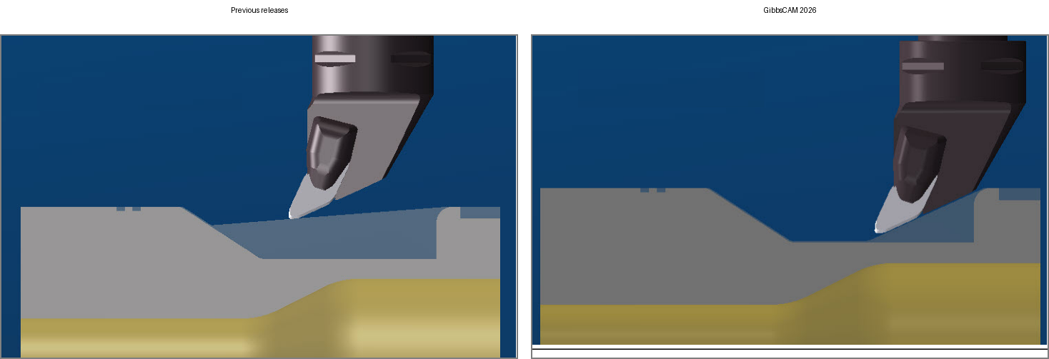
Figure 1 GibbsCAM 2026 uses more of the insert shape while preserving safety
Source: What's New in GibbsCAM 2026, p. 14
Step 3 - Use a Non-Round Insert in VoluTurn
1. Create or copy a supported VoluTurn operation and select the validated non-round insert.
2. Regenerate the toolpath and review engagement, stock removal, clearance, and the completed profile.
3. If the tool is unavailable or the operation does not calculate, verify the insert definition and licensed VoluTurn configuration before changing geometry.
Step 4 - Validate the Operation
1. Run complete Machine Simulation with the physical insert, holder, fixtures, stock, and machine components.
2. Inspect tool contact and remaining stock, then review posted motion and cutting-edge use.
3. Complete controlled prove-out before releasing the updated toolpath for production.
Expected Result
• The multi-sided turning path removes the intended material without reducing collision protection.
• The supported non-round insert calculates and simulates in the VoluTurn operation.
• Simulation and posted output agree with the approved tool definitions and machining plan.
Related Video
Best Practices
• Import or build the complete insert and holder geometry; do not substitute a generic tool shape.
• Compare remaining stock before changing cutting parameters.
• Validate Prime-style and VoluTurn insert workflows separately.
• Revalidate after changes to the insert, holder, operation, MDD, or post.
Troubleshooting
• Problem: The multi-sided operation still leaves unexpected material.
Cause
• The operation was not regenerated in GibbsCAM 2026.
• The insert definition does not represent the intended nonconvex shape or orientation.
Resolution
Verify the insert and holder definitions, regenerate the operation, and compare tool contact and remaining stock with the baseline before changing cutting geometry.
• Problem: The updated path approaches a gouge or collision.
Cause
• The insert, holder, stock, fixture, or machine geometry is incomplete.
• The selected cutting edge, orientation, clearance, or containment is incorrect.
Resolution
Stop release. Correct the complete setup, restore conservative values, regenerate, and repeat full Machine Simulation and posted-code review.
• Problem: VoluTurn does not accept the selected non-round insert.
Cause
• The licensed product or installed build does not provide the required capability.
• The insert definition is incomplete, unsupported, or incompatible with the operation.
Resolution
Confirm GibbsCAM 2026 and the VoluTurn product, then replace or correct the insert definition with a CAMCO-validated tool and regenerate the operation.
• Problem: Simulation and posted motion do not agree.
Cause
• The simulation setup, machine definition, post, or coordinate systems do not match production.
• The posted workflow uses different tool or cutting-edge data than the operation.
Resolution
Stop release. Confirm the physical tool, qualified MDD and post, coordinate systems, and tool selection. Re-simulate and repost before controlled prove-out.
Related Articles
• Recommended Simulation Settings
• How to Create a Pack and Go File
Explore More from CAMCO
Visit the CAMCO website to learn more about:
• Downloads and Helpful Resources
Keywords
GibbsCAM 2026, Turning, multi-sided turning tool, MST, nonconvex insert, CoroTurn Prime, Prime A, Prime B, VoluTurn, non-round insert, material calculation
Was this article helpful?
That’s Great!
Thank you for your feedback
Sorry! We couldn't be helpful
Thank you for your feedback
Feedback sent
We appreciate your effort and will try to fix the article