Summary
GibbsCAM 2026 improves supported Deburring operations with Automatic Machining Direction, user-defined edge order, and consolidated 3+2 behavior. Use these controls to organize edge machining, reduce unnecessary simultaneous 5-axis motion, and produce a sequence that matches the job requirement.
Table of Contents
What Changed in GibbsCAM 2026
Important: A logical displayed sequence does not confirm safe machine motion. Validate links, clearance, rotary travel, and machine reach with the complete production setup.
Before You Begin
• Use GibbsCAM 2026 with the required 5-Axis and supported Deburring or Multi-Axis Edge Finishing capability.
• Use a CAMCO-approved machine definition and production postprocessor.
• Define accurate edges, stock, tools, holders, fixtures, and machine limits.
• Save a copy of the part and retain the current operation as a calculated baseline.
Procedure
Step 1 - Record the Baseline
1. Duplicate the affected Deburring operation.
2. Record the selected edges, selection order, direction, tool-axis settings, links, and estimated cycle time.
3. Calculate and simulate the baseline for comparison.
Step 2 - Choose the Machining Direction
1. Open 5-Axis > Deburring, then go to Surface paths > Path parameter > Direction.
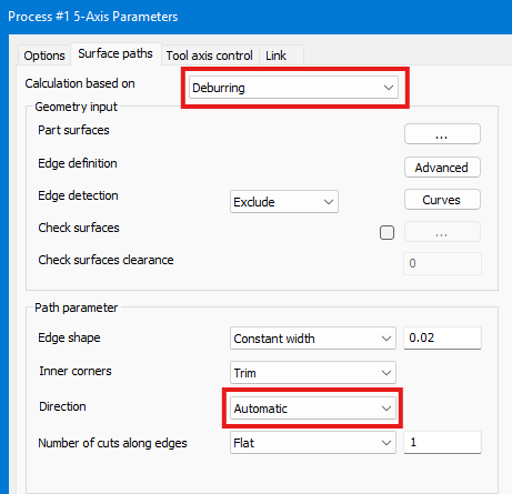
2. Use Automatic Machining Direction when GibbsCAM should determine direction from the contour definition.
3. Regenerate and review direction, edge transitions, links, and cycle time.
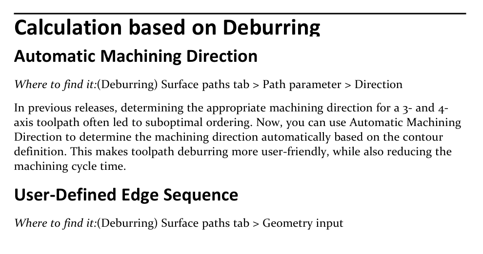
Figure 1 Automatic direction uses the contour definition
Source: What's New in GibbsCAM 2026, p. 43
Step 3 - Preserve the Selected Edge Order
1. Go to Surface paths > Geometry input, select the curves or edges in the required order, and preserve the input order.
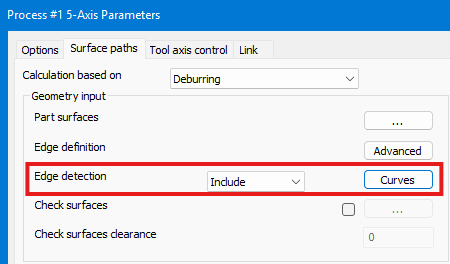
2. Select or reorder the included curves in the required machining sequence.
3. Regenerate and confirm that the calculated path follows the intended edge order.
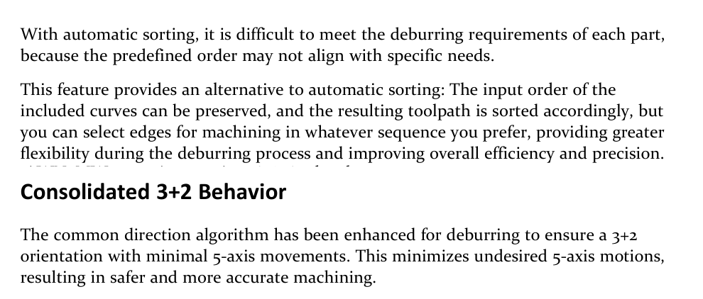
Figure 2 Preserve edge order and minimize unnecessary simultaneous motion
Source: What's New in GibbsCAM 2026, p. 44
Step 4 - Review Consolidated 3+2 Motion
1. Inspect the calculated orientations and confirm that fixed 3+2 positions are consolidated where practical.
2. Compare simultaneous 5-axis movement, rotary repositioning, links, and cycle time with the baseline.
3. Revise direction or sequence only when the alternative remains safe and produces the required result.
Step 5 - Validate the Output
1. Run Op Simulation and Machine Simulation with the production stock, fixtures, tool, and holder.
2. Review every cut, link, rotary move, machine limit, and potential singularity.
3. Post with the approved postprocessor and complete the shop's controlled prove-out before production release.
Expected Result
• The operation follows the approved machining direction and edge order.
• Consolidated 3+2 behavior reduces unnecessary simultaneous 5-axis motion where practical.
• All cutting, linking, rotary, and posted motion remains collision-free and within machine limits.
Best Practices
• Change direction and edge order separately, and retain the baseline until the revised sequence is approved.
• Inspect links and rotary repositioning, not only the cutting path.
• Revalidate after any geometry, tool, fixture, machine, or postprocessor change.
Troubleshooting
• Problem: Automatic direction produces the wrong order or travel direction.
Cause
• The contour definition or included-curve order does not match the intended machining sequence.
• Automatic direction is unsuitable for the local geometry or setup requirement.
Resolution
Correct the selected geometry and curve order, or use a validated manual direction. Regenerate and compare the complete path with the baseline.
• Problem: The selected edge order is not preserved.
Cause
• Preserve-input-order behavior is not active.
• The included curves were selected in a different order or the operation was not fully regenerated.
Resolution
Repair the geometry, reselect the curves or edges in the required order, and fully recalculate before reviewing the result.
• Problem: The operation still uses unnecessary simultaneous 5-axis motion.
Cause
• The geometry requires changing tool orientations or cannot be consolidated into common 3+2 positions.
• Direction, edge order, or tool-axis settings prevent useful consolidation.
Resolution
Review direction, sequence, and tool-axis settings. Accept simultaneous motion only after confirming it is required and safe for the approved machine and post.
• Problem: Links or rotary moves exceed clearance or machine reach.
Cause
• The revised sequence creates unsuitable transitions or rotary repositioning.
• Fixture, holder, machine-limit, or postprocessor data is incomplete or incorrect.
Resolution
Stop release. Correct the complete setup, revise the sequence or links, and rerun full Machine Simulation and posted-code review.
Related Articles
• How to Machine Open Shapes in GibbsCAM
• Recommended Simulation Settings
• How to Create a Pack and Go File
Explore More from CAMCO
Visit the CAMCO website to learn more about:
• Downloads and Helpful Resources
Keywords
GibbsCAM 2026, 5-Axis Deburring, Multi-Axis Edge Finishing, Automatic Machining Direction, user-defined edge order, consolidated 3+2, included curves
Was this article helpful?
That’s Great!
Thank you for your feedback
Sorry! We couldn't be helpful
Thank you for your feedback
Feedback sent
We appreciate your effort and will try to fix the article