Summary
GibbsCAM 2025 adds Corner Arc Support for chamfer tools in 5-axis deburring. Supported paths can remain continuous around inner and outer corners without intermediate links, reducing noncutting motion during chamfering.
Table of Contents
What Changed in GibbsCAM 2025
Important: The release notes describe the result but do not provide an option path. Confirm the supported strategy, control availability, and exact interface in the installed GibbsCAM 2025 build.
Before You Begin
• Use GibbsCAM 2025 with the applicable 5-Axis product and deburring strategy.
• Define the physical chamfer mill, shaft, holder, stock, fixtures, and machine limits accurately.
• Select representative inner and outer corners, including any tight or interrupted edges.
• Save the current path, simulation result, cycle time, and posted program as a baseline.
Procedure
Step 1 - Establish a Corner Baseline
1. Copy an existing 5-axis edge-finishing or deburring operation that uses a chamfer mill.
2. Regenerate and record where the baseline inserts links or interrupts motion at corners.
3. Inspect edge selection, direction, tool orientation, clearance, and posted rotary motion.
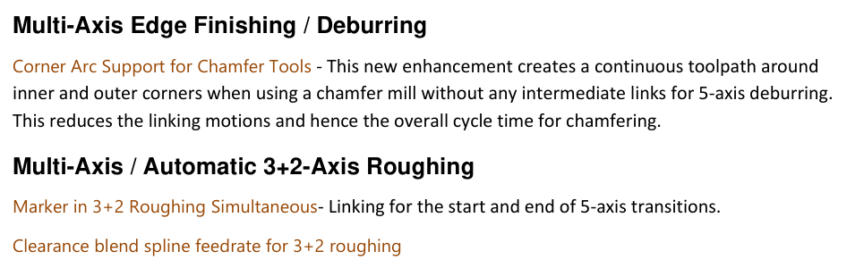
Figure 1 Review continuous corner arcs and 3+2 transition items
Source: What's New in GibbsCAM 2025, p. 36
Step 2 - Apply Corner Arc Support
1. Use the Corner Arc Support behavior provided by the supported GibbsCAM 2025 deburring strategy.
2. Regenerate the operation across representative inner and outer corners.
3. Confirm that the chamfer path remains continuous where the geometry and strategy support the new behavior.
Step 3 - Inspect Corner Quality and Motion
1. Inspect chamfer coverage, corner blending, tool contact, and direction through every selected corner.
2. Review holder and shaft clearance, feed continuity, rotary travel, and remaining stock.
3. Compare link count and cycle time with the baseline without accepting a gouge or loss of coverage.
Step 4 - Validate the Operation
1. Run complete Machine Simulation with the full tool assembly, fixtures, stock, and machine components.
2. Post the operation and review all cutting, linking, and rotary motion.
3. Complete controlled prove-out before releasing the continuous-corner path for production.
Expected Result
• Supported inner and outer corners use continuous chamfer-mill motion without intermediate links.
• Chamfer coverage and corner quality remain complete and consistent.
• Simulation and posted output show safe clearance and reachable rotary motion.
Best Practices
• Test both inner and outer corners before accepting the new behavior.
• Use the exact chamfer-mill, shaft, and holder geometry.
• Reduce links only when coverage, clearance, and feed continuity remain acceptable.
• Revalidate after changes to edges, tolerance, tool, strategy, MDD, or post.
Troubleshooting
• Problem: Corner Arc Support is unavailable.
Cause
• The active strategy or build does not support the behavior.
• The operation is not using the required 5-axis product or chamfer tool.
Resolution
Confirm the installed build, licensed products, strategy, and chamfer-mill definition. Send CAMCO the sample file and build details if the supported control remains unclear.
• Problem: The path inserts links at a corner.
Cause
• The corner geometry, edge selection, or direction creates an interruption.
• The selected tool, tolerance, or orientation does not support continuous motion at that corner.
Resolution
Verify and repair the selected edges, confirm the chamfer-mill definition, and regenerate. Compare the corner with the baseline before changing tolerance or orientation.
• Problem: The continuous path gouges or loses chamfer coverage.
Cause
• The tool contact, edge geometry, offset, or orientation is incorrect.
• The corner is too tight for the tool and selected motion.
Resolution
Stop release, restore the baseline, verify the edge and tool data, and use a safer orientation or separate motion. Repeat complete simulation before prove-out.
• Problem: Posted corner motion is abrupt or exceeds a rotary limit.
Cause
• The machine definition, post, coordinate systems, or rotary limits do not match the setup.
• The continuous path requires a rotary transition the machine cannot reach smoothly.
Resolution
Confirm the qualified MDD and post, inspect every rotary transition, and revise the operation or split the path where needed. Repost and prove out the corrected motion.
Related Articles
• How to Machine Open Shapes in GibbsCAM
• Recommended Simulation Settings
• How to Create a Pack and Go File
Explore More from CAMCO
Visit the CAMCO website to learn more about:
• Downloads and Helpful Resources
Keywords
GibbsCAM 2025, 5-axis deburring, Corner Arc Support, chamfer mill, inner corner, outer corner, continuous toolpath, edge finishing, link reduction
Was this article helpful?
That’s Great!
Thank you for your feedback
Sorry! We couldn't be helpful
Thank you for your feedback
Feedback sent
We appreciate your effort and will try to fix the article