Summary
GibbsCAM 2025 adds Sort by Regions/Lanes for supported finishing cycles and two lead controls for multi-axis surfaces. Tool Orientation Normal To Lead keeps the tool normal to the toolpath through the lead, while Along Tool Axis follows the tool-axis direction. AutoTilt 2.0 also supports automatic arc leads with automatic tool orientation and barrel tools.
Table of Contents
What Changed in GibbsCAM 2025
Important: The source page also lists several controls without descriptions, including 3D Containment Curve Offset and Advanced Run tool at contact point. They are excluded until CAMCO confirms their scope and interface.
Before You Begin
• Use GibbsCAM 2025 with the applicable Multi-Axis product, finishing strategy, and license.
• Define the part, containment, tool, shaft, holder, fixtures, coordinate systems, and machine limits accurately.
• For AutoTilt 2.0 testing, use a qualified barrel-tool definition and automatic tool orientation.
• Save the current cut order, lead motion, simulation result, cycle time, and posted output as a baseline.
Procedure
Step 1 - Compare Finishing Order
1. Open a supported finishing cycle and review the current region and lane order.
2. Select Sort by Regions/Lanes and regenerate the operation.
3. Compare coverage, travel between regions, linking motion, and cycle time with the baseline.
Step 2 - Set Lead Orientation
1. Use Tool Orientation Normal To Lead when the tool must remain normal to the toolpath at every point of the lead.
2. Use Along Tool Axis when the lead must follow the tool-axis direction.
3. Test one lead type at a time and inspect the entire approach, transition, and departure.
Step 3 - Evaluate AutoTilt 2.0
1. Use a supported automatic arc lead, automatic tool orientation, and a verified barrel tool.
2. Enable the available AutoTilt 2.0 behavior and regenerate the operation.
3. Inspect tool contact, clearance, rotary travel, singularities, and machine limits through the complete lead motion.
Step 4 - Validate the Operation
1. Confirm that the selected order machines every required region once and does not add unsafe travel.
2. Run complete Machine Simulation with the full setup and machine components.
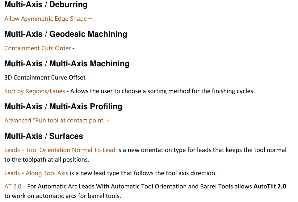
Figure 1 Apply documented finishing and lead controls; validate abbreviated entries
Source: What's New in GibbsCAM 2025, p. 36
3. Post the operation, review all lead and rotary motion, and complete controlled prove-out before release.
Expected Result
• The finishing cycle uses the intended region or lane order without losing coverage.
• Lead motion follows the selected toolpath-normal or tool-axis direction.
• AutoTilt 2.0 produces reachable, collision-free motion for the supported barrel-tool setup.
Best Practices
• Compare one sorting or lead control at a time with the saved baseline.
• Choose cut order from the geometry and machining plan rather than cycle time alone.
• Use complete barrel-tool, shaft, holder, and machine-limit data for AutoTilt testing.
• Revalidate after changes to containment, tool, strategy, MDD, or post.
Troubleshooting
• Problem: Sort by Regions or Lanes is unavailable or produces inefficient travel.
Cause
• The active strategy or build does not support the sorting method.
• The selected order does not suit the region and lane layout.
Resolution
Confirm the supported finishing cycle, restore the baseline, and compare each available sorting method separately. Retain the order that preserves coverage and safe motion.
• Problem: Tool Orientation Normal To Lead changes orientation unexpectedly.
Cause
• The lead path, surface normal, or tool orientation data is unsuitable.
• Avoidance settings or machine limits modify the calculated orientation.
Resolution
Verify the lead geometry and setup, restore the baseline, and test Normal To Lead alone. Inspect the full transition in simulation and posted output.
• Problem: Along Tool Axis creates an unsafe approach or departure.
Cause
• The tool-axis direction does not provide enough clearance for the local geometry.
• The tool, holder, fixture, or machine model is incomplete.
Resolution
Stop release, complete the setup definitions, and return to the baseline lead. Use an alternate lead or approved clearance values and repeat full simulation.
• Problem: AutoTilt 2.0 is unavailable or creates abrupt rotary motion.
Cause
• The operation is not using automatic arc leads, automatic orientation, and a supported barrel tool.
• Tool geometry, avoidance data, singularities, or machine limits prevent a smooth result.
Resolution
Confirm the required strategy and tool configuration, correct the complete setup, then test AutoTilt 2.0 independently. Re-simulate and review posted rotary motion before prove-out.
Related Articles
• How to Machine Open Shapes in GibbsCAM
• Recommended Simulation Settings
• How to Create a Pack and Go File
Explore More from CAMCO
Visit the CAMCO website to learn more about:
• Downloads and Helpful Resources
Keywords
GibbsCAM 2025, multi-axis finishing, Sort by Regions, Sort by Lanes, lead orientation, Normal To Lead, Along Tool Axis, AutoTilt 2.0, barrel tool
Was this article helpful?
That’s Great!
Thank you for your feedback
Sorry! We couldn't be helpful
Thank you for your feedback
Feedback sent
We appreciate your effort and will try to fix the article