Summary
GibbsCAM 2025 expands multi-axis and rotary roughing with strict automatic tilting, rotary lead-in and lead-out motion, area-roughing link and ramp controls, geodesic smoothing and medial-axis cuts, and new advanced-tool and swarf options. Test each control independently because the required strategy, tool definition, and collision model vary.
Table of Contents
What Changed in GibbsCAM 2025
Important: These controls are strategy-specific. Automatic tilting and selective collision checking require complete tool, holder, stock, fixture, and machine data. Confirm exact labels and availability in the installed build.
Before You Begin
• Use GibbsCAM 2025 with the applicable Multi-Axis or Rotary Roughing products and licenses.
• Prepare separate nonproduction operations for tilting, rotary, area, geodesic, advanced-tool, or swarf testing as applicable.
• Define the part, stock, tool, shaft, holder, fixtures, coordinate systems, machine limits, and post accurately.
• Save a baseline path, simulation result, cycle time, and posted program before enabling a new control.
Procedure
Step 1 - Apply Strict Automatic Tilting
1. Open an approved operation and go to Gouge Check. Enable Tilt Tool and Automatic.
2. Open Parameters > Behavior > Preference and select Rotary tilt (strict) only when the input table rotation must remain constant while the tilt axis avoids collisions.
3. Regenerate and inspect table reversals, tilt-axis travel, singularities, machine limits, and clearance.
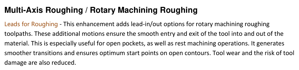
Figure 1 Add controlled lead-in and lead-out motions to rotary roughing
Source: What's New in GibbsCAM 2025, p. 34
Step 2 - Add Rotary Roughing Leads
1. Open the lead settings for a supported Rotary Machining Roughing operation.
2. Add approved lead-in and lead-out motion for an open pocket or rest-machining path that needs smoother entry and exit.
3. Regenerate and inspect the start point, engagement, clearance, and exit motion on every open contour.
Step 3 - Tune Area and Geodesic Roughing
1. In Area Roughing, test Minimize Links, Avoid Small Profile Ramp, and Trim Line Ramps one at a time. Match minimum ramp size to the cutter geometry and keep in-process stock current.
2. In Geodesic Machining, test Improved Corner Smoothing separately from additional medial-axis cuts. Choose whether the added cuts merge with the main path or act as finishing cuts.
3. Compare ramp count, engagement, cusps, acceleration changes, stock contact, and cycle time with the baseline.
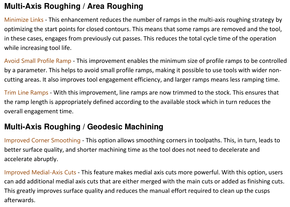
Figure 2 Review area and geodesic roughing improvements
Source: What's New in GibbsCAM 2025, p. 35
Step 4 - Configure Advanced Tools and Swarf Checks
1. For wall, floor, or rest finishing with a barrel or other advanced tool, define stepover by cusp height only after verifying the complete tool geometry.
2. Use Tool Segment Selection for Tilting to control the allowed tool segment, tilting range, and contact region. Define slot-mill chamfered edges only when they match the physical cutter.
3. For swarf machining, select individual tool parts for gouge checking only when every excluded component is proven unable to contact the setup.
Step 5 - Validate the Operation
1. Run complete Machine Simulation with current stock, fixtures, tool, holder, and machine components.
2. Compare the result with the saved baseline without reducing required clearance or stock removal.
3. Post the operation, review all linear and rotary motion, and complete controlled prove-out before production release.
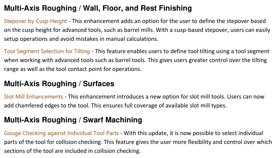
Figure 3 Use complete tool data for advanced-tool and swarf controls
Source: What's New in GibbsCAM 2025, p. 35
Expected Result
• Strict tilting maintains the intended table rotation while avoiding collisions with the tilt axis.
• Rotary leads and area-roughing ramps enter and leave material smoothly and safely.
• Area and geodesic controls reduce unnecessary links or abrupt motion while preserving required stock removal.
• Advanced-tool contact and swarf gouge checks match the physical assembly and simulated result.
Best Practices
• Change one control at a time and retain a known-good operation for comparison.
• Use the actual tool, shaft, holder, chamfer, and cutting-segment geometry.
• Update in-process stock before evaluating trimmed ramps or reused passes.
• Revalidate after changes to geometry, tool, stock, strategy, MDD, or post.
Troubleshooting
• Problem: Rotary tilt strict is missing or produces unexpected axis motion.
Cause
• Tilt Tool and Automatic are not both active, or the selected strategy does not support the preference.
• The input rotary orientation, machine limits, avoidance geometry, or tool assembly is incorrect.
Resolution
Confirm Gouge Check > Tilt Tool > Automatic and the machine setup. Restore the baseline, correct geometry and limits, then re-enable Rotary tilt (strict) and inspect every transition.
• Problem: Rotary leads or area-roughing ramps are unsafe.
Cause
• The lead, minimum profile-ramp size, or trimmed line ramp does not suit the tool and available stock.
• In-process stock or open-contour geometry is incomplete.
Resolution
Correct the stock and tool definitions, return to conservative entry values, and test one lead or ramp control at a time. Simulate every entry and exit.
• Problem: Corner smoothing or medial-axis cuts leave cusps or add unwanted motion.
Cause
• The smoothing or additional-cut settings are too aggressive for the geometry.
• The operation uses an unsuitable tolerance, tool, stepover, or finishing assignment.
Resolution
Restore the Geodesic baseline, verify the tool and tolerance, then add smoothing or medial-axis cuts separately. Compare coverage, remaining stock, and posted motion.
• Problem: Advanced-tool contact or swarf gouge checking is unreliable.
Cause
• The physical tool does not match the barrel, slot-mill chamfer, tool segment, shaft, or holder definition.
• A tool component that can contact the setup was excluded from gouge checking.
Resolution
Correct the complete assembly, include every relevant tool part in collision checks, regenerate, and run full Machine Simulation. Resolve all unexplained contact before release.
Related Articles
• Recommended Simulation Settings
• How to Create a Pack and Go File
Explore More from CAMCO
Visit the CAMCO website to learn more about:
• Downloads and Helpful Resources
Keywords
GibbsCAM 2025, Multi-Axis Roughing, Rotary Roughing, Rotary tilt strict, automatic tilting, rotary leads, Minimize Links, profile ramp, Geodesic Machining, medial-axis cuts, cusp height, barrel mill, tool segment, swarf gouge checking
Was this article helpful?
That’s Great!
Thank you for your feedback
Sorry! We couldn't be helpful
Thank you for your feedback
Feedback sent
We appreciate your effort and will try to fix the article