Summary
GibbsCAM 2026 adds a conical-floor angle control, lead-in and lead-out for rotary floor finishing, fixture and chuck profiles for rotary collision avoidance, and containment trim for Rotary Finishing.
Table of Contents
What Changed in GibbsCAM 2026
Important: A spun fixture or chuck profile is only as accurate as the selected model and offset. Validate leads, containment, collisions, rotary limits, and posted motion with the complete production setup.
Before You Begin
• Use GibbsCAM 2026 with the required 5-Axis and supported Rotary Roughing or Finishing capability.
• Use a CAMCO-approved rotary machine definition and production postprocessor.
• Define accurate part, stock, tool, holder, fixture, chuck, containment, and rotary-axis data.
• Save a copy of the part and retain the current rotary operations as a baseline.
Procedure
Step 1 - Record the Baseline
1. Duplicate the affected rotary operation.
2. Record the selected geometry, tool orientation, leads, containment, fixtures, offsets, rotary limits, and estimated cycle time.
3. Calculate and simulate the baseline for comparison.
Step 2 - Configure Rotary Floor Finishing
1. In Rotary Machining Finishing, open the Surface paths Tool orientation area.
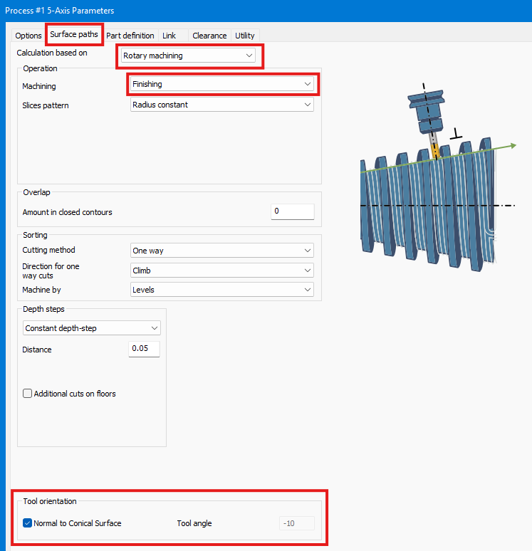
2. Define the conical-floor detection angle and choose the required stationary or tilted milling-head result.
3. Under Part definition > Link > Contour Leads, define lead-in and lead-out for the cylindrical or conical floor-finishing pattern.
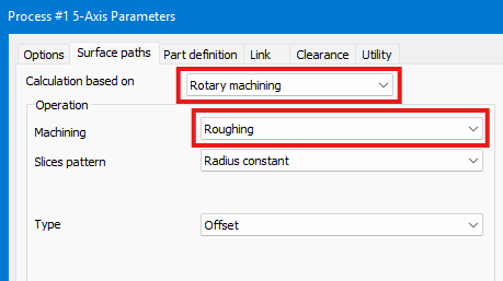
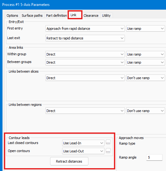
4. Regenerate and inspect floor detection, tool orientation, entry, exit, and tool marks.
Step 3 - Include Fixtures and Chucks
1. For rotary roughing or finishing, open Part definition > Machining surfaces > Fixture.
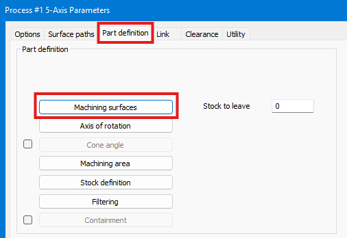
2. Select every required fixture or chuck mesh or model and set a conservative offset distance.
3. Regenerate and confirm that the spun profile is included in collision avoidance along the complete path.
Step 4 - Apply Containment Trim
1. For Rotary Finishing, open Part definition > Containment > Trim.
2. Enable trim when the tool center should stop as it reaches the containment region.
3. Regenerate and verify boundary coverage and removal of unwanted extensions beyond containment.
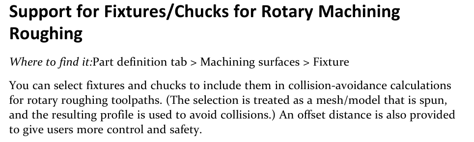
Figure 1 Include selected fixture or chuck profiles in rotary collision avoidance
Source: What's New in GibbsCAM 2026, p. 42
Step 5 - Validate the Result
1. Compare entry, exit, surface quality, boundary coverage, clearance, and cycle time with the baseline.
2. Run Op Simulation and Machine Simulation with the production fixture, chuck, tool, and holder.
3. Post with the approved postprocessor and review rotary motion, reversals, singularities, and machine limits before controlled prove-out.
Expected Result
• Conical floors are detected and finished with the intended tool orientation.
• Leads provide reviewed entry and exit without unacceptable tool marks.
• Fixture and chuck profiles remain clear, and containment trim stops the finishing path at the intended boundary.
Best Practices
• Validate floor orientation, leads, fixtures, and containment one change at a time.
• Select every production fixture and chuck and use conservative offsets.
• Inspect the complete spun profile instead of checking only a single rotary position.
• Verify posted rotary motion and machine limits before controlled prove-out.
Troubleshooting
• Problem: A conical floor is not detected or uses the wrong orientation.
Cause
• The floor-detection angle or Tool orientation setting is incorrect.
• The selected surface is unsuitable or the operation is not supported Rotary Finishing.
Resolution
Verify the conical surface and supported operation, correct the detection angle and tool orientation, then recalculate and inspect contact.
• Problem: Floor-finishing leads leave marks or enter unsafely.
Cause
• The lead type, size, direction, or available clearance is unsuitable.
• The tool, stock, fixture, or containment definition is inaccurate.
Resolution
Correct the complete setup, reduce or revise the leads, and simulate each entry and exit before posting.
• Problem: The toolpath approaches a fixture or chuck.
Cause
• The required mesh or model was not selected or its position is wrong.
• The collision-avoidance offset is too small or the rotary setup is incorrect.
Resolution
Stop release. Correct the selected fixture or chuck and its offset, regenerate, and inspect the complete spun profile in Machine Simulation.
• Problem: Containment trim removes too much path or leaves unwanted extensions.
Cause
• The containment boundary does not match the required finished region.
• Trim behavior is unsuitable for the tool-center path, leads, or local geometry.
Resolution
Correct the containment and review leads, then recalculate and verify boundary coverage and stock removal in simulation.
Related Articles
• Recommended Simulation Settings
• How to Create a Pack and Go File
Explore More from CAMCO
Visit the CAMCO website to learn more about:
• Downloads and Helpful Resources
Keywords
GibbsCAM 2026, 5-Axis, Rotary Machining, Rotary Finishing, conical floor, Tool orientation, Contour Leads, fixture, chuck, collision avoidance, containment trim
Was this article helpful?
That’s Great!
Thank you for your feedback
Sorry! We couldn't be helpful
Thank you for your feedback
Feedback sent
We appreciate your effort and will try to fix the article