Summary
GibbsCAM 2024 adds a Generate toolpath from menu for 2D Form and 3D Form Mill tools. Real profile, Monotonic profile, and Nominal parameters provide different contact-point calculations while preserving the actual tool profile for rendering whenever possible.
Table of Contents
- What Changed in GibbsCAM 2024
- Before You Begin
- Procedure
- Related Video
- Best Practices
- Troubleshooting
- Related Articles
What Changed in GibbsCAM 2024
Important: These choices change contact-point calculation for toolpath generation. Material Only and Rendering use the real tool profile whenever possible.
Before You Begin
• Use GibbsCAM 2024 or later and open a backup copy of the part file.
• Select a Mill tool defined as 2D Form or 3D Form.
• Obtain the manufacturer's tool geometry and programming guidance.
• For Nominal parameters, obtain the approved nominal diameter and programming or virtual corner radius.
Procedure
Step 1 - Open the Mill Form Tool
1. Open the Tools dialog and select the intended 2D Form or 3D Form Mill tool.
2. Confirm the actual tool profile and dimensions against the manufacturer record.
3. Locate the Generate toolpath from menu.
Step 2 - Choose the Contact Model
1. Choose Real profile for the most accurate calculation from the actual cutter form. This default matches earlier releases but requires the most computation.
2. Choose Monotonic profile to disable undercutting where the tool narrows. GibbsCAM uses the widest contact radius below the geometry depth to preserve shank clearance.
3. Choose Nominal parameters when the manufacturer supplies a simplified nominal diameter and programming radius for calculating the cutter as a bullnose mill.
Step 3 - Enter Nominal Parameters When Required
1. Enter the manufacturer-supplied Nominal Diameter.
2. Enter the approved Virtual Corner Radius.
3. Confirm that the simplified bullnose calculation is appropriate for the specific cutter and application.
Step 4 - Regenerate and Verify
1. Apply the tool changes and regenerate every affected operation.
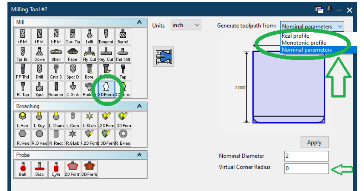
Figure 1 Choose the contact-calculation profile for a 2D Form or 3D Form Mill Tool
Source: What's New in GibbsCAM 2024, p. 15
2. Inspect contact behavior, shank clearance, calculation time, and any change from the previous toolpath.
3. Render or simulate the operation, review the posted output, and complete the normal shop prove-out before production use.
Expected Result
• The selected profile controls the contact model used to generate the toolpath.
• Real profile uses the actual cutter form, Monotonic profile suppresses undercut behavior, and Nominal parameters calculate as a bullnose mill.
• Rendering shows the actual tool profile whenever possible, including when a simplified calculation model is selected.
Related Video
Best Practices
• Use Real profile as the accuracy baseline when evaluating another contact model.
• Use Monotonic profile only when its undercut restriction matches the intended cutter engagement.
• Use Nominal parameters only with values supplied or approved for the specific cutter and application.
• Compare regenerated toolpaths with a saved baseline before changing proven production work.
Troubleshooting
• Problem: The Mill Form Tool calculates slowly.
Cause
• Real profile is selected and the detailed cutter form requires more contact calculations.
• The tool profile or affected geometry contains unnecessary detail.
Resolution
Confirm the tool definition and operation geometry. Keep Real profile when its accuracy is required; use another profile only when the manufacturer's programming guidance supports it, then regenerate and validate the result.
• Problem: The toolpath undercuts or approaches the shank unexpectedly.
Cause
• Real profile allows contact with narrowing regions of the tool.
• The selected profile does not match the required clearance behavior.
Resolution
Review the tool profile, geometry depth, and clearance. Compare the result with Monotonic profile, which disables undercutting where the tool narrows, and validate the complete toolpath before use.
• Problem: The rendered tool shape differs from the simplified Nominal toolpath model.
Cause
• Nominal parameters calculate contact as a bullnose mill while Rendering uses the actual tool profile whenever possible.
• The Nominal Diameter or Virtual Corner Radius does not match the manufacturer guidance.
Resolution
Confirm that the visual difference is expected, then verify the nominal diameter and virtual corner radius. Regenerate, simulate with the actual tool profile, and reject the result if clearance or engagement cannot be validated.
Related Articles
• Recommended Simulation Settings
Explore More from CAMCO
Visit the CAMCO website to learn more about:
• Downloads and Helpful Resources
Keywords
GibbsCAM 2024, Mill Form Tool, 2D Form, 3D Form, Real profile, Monotonic profile, Nominal parameters, Virtual Corner Radius, high-feed mill
Was this article helpful?
That’s Great!
Thank you for your feedback
Sorry! We couldn't be helpful
Thank you for your feedback
Feedback sent
We appreciate your effort and will try to fix the article