Summary
GibbsCAM 2024 identifies tools that contain attached feeds and speeds. A checkmark appears on the Cutting Data button in the Tool dialog and on the Tool button in processes that use the tool. Either checked button opens the attached data for review or editing.
Table of Contents
- What Changed in GibbsCAM 2024
- Before You Begin
- Procedure
- Related Video
- Best Practices
- Troubleshooting
- Related Articles
What Changed in GibbsCAM 2024
Important: A checkmark confirms that cutting data is attached; it does not confirm that the values are correct for the material, machine, tool assembly, or operation.
Before You Begin
• Use GibbsCAM 2024 or later and open a backup copy of the part file.
• Select the intended tool and confirm which processes use it.
• Have the current manufacturer data and approved shop standards available for comparison.
• Confirm the job units, work material, cutter grade, and intended application before changing any value.
Procedure
Step 1 - Check the Tool Dialog
1. Open the Tool dialog for the intended tool.
2. Locate the Cutting Data button. A checkmark indicates that feeds and speeds are attached to the tool.
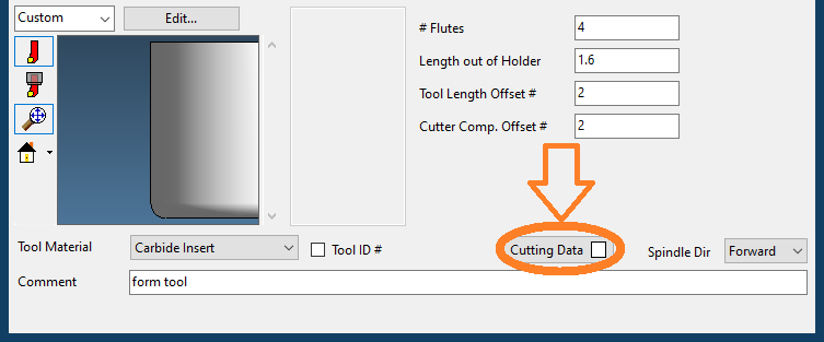
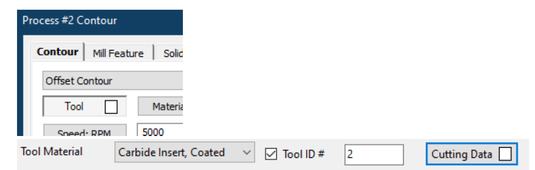
Figure 1 The Tool and Cutting Data buttons provide access to data associated with the selected tool
Source: What's New in GibbsCAM 2024, p. 16
3. If no checkmark appears, confirm that the correct tool is open before assuming that data is missing.
Step 2 - Check a Process That Uses the Tool
1. Open a process that uses the selected tool.
2. Locate the Tool button. A checkmark indicates that the process can access cutting data attached to its assigned tool.
3. Verify the assigned tool if the process indicator differs from the Tool dialog indicator.
Step 3 - Review or Change the Data
1. Click either checked button to open the attached cutting data.
2. Review the values, units, cutter, grade, work material, and application against the approved source.
3. Change values only when the revised data has been approved for the tool, material, machine, and operation.
Step 4 - Recalculate and Validate
1. Save the tool changes and recalculate every affected operation.
2. Review the resulting spindle speed and feed values, then simulate the affected operations.
3. Post with the approved post processor and complete the normal shop prove-out before production use.
Expected Result
• The Tool dialog and processes that use the tool show consistent attached-data indicators.
• Either checked button opens the cutting data attached to the selected tool.
• Recalculated operations use reviewed values that match the approved units and application.
Related Video

Best Practices
• Treat imported or attached cutting data as a reviewed starting point, not automatic production approval.
• Record the tool source, grade, work material, application, and revision date in controlled shop documentation.
• Verify units before changing any diameter, radius, feed, speed, or chip-load value.
• Recalculate and reapprove every affected process after changing tool-level data.
Troubleshooting
• Problem: The Cutting Data button has no checkmark.
Cause
• The selected tool has no feeds and speeds attached.
• A different tool is open than the one expected.
Resolution
Confirm the selected tool and its source. Import or select the intended tool with supported cutting data, or enter approved values through the normal shop workflow, then reopen the Tool dialog.
• Problem: The process Tool button has no checkmark even though another tool contains cutting data.
Cause
• The process is assigned to a different tool.
• The expected tool-level data was not saved before the process was reopened.
Resolution
Confirm the tool assigned to the process, save the intended tool definition, and reopen the process. Recalculate after the indicators agree.
• Problem: The attached values are unexpected or use the wrong units.
Cause
• The tool was imported with data for a different application or unit system.
• The attached record was changed without updating the controlled shop reference.
Resolution
Do not release the operation. Compare the tool, units, material, grade, and values with the current manufacturer record and approved shop standard, then correct or replace the data and recalculate.
Related Articles
• How to Save and Load Process or Tool Lists
Explore More from CAMCO
Visit the CAMCO website to learn more about:
• Downloads and Helpful Resources
Keywords
GibbsCAM 2024, Cutting Data, feeds and speeds, Tool dialog, process Tool button, attached cutting data, imported tool, tool list
Was this article helpful?
That’s Great!
Thank you for your feedback
Sorry! We couldn't be helpful
Thank you for your feedback
Feedback sent
We appreciate your effort and will try to fix the article