Summary
GibbsCAM 2025 adds Rib Cut Plunge to Turning Rough processes. The strategy creates a preliminary series of full-engagement plunges, with each cut more than one tool width from the previous cut. A following pass removes the remaining ribs. The release notes describe the pattern as a way to reduce tool deflection and improve chip control.
Table of Contents
- What Changed in GibbsCAM 2025
- Before You Begin
- Procedure
- Related Video
- Best Practices
- Troubleshooting
- Related Articles
What Changed in GibbsCAM 2025
Important: The values shown in the release notes are examples, not production recommendations. Use approved values for the tool, material, machine, and setup, then complete controlled prove-out.
Before You Begin
• Use GibbsCAM 2025 with the approved machine definition, production post, and licensed Turning module.
• Select a suitable turning roughing tool and verify insert geometry, holder clearance, tool overhang, and machine power.
• Confirm the stock, profile, material, spindle direction, cut direction, allowances, feeds, speeds, and clearances.
• Save a working copy and retain a baseline operation using the shop's established roughing strategy.
Procedure
Step 1 - Prepare the Turning Rough Process
1. Create or edit a Turning Rough process and select the approved roughing tool.
2. Verify the part profile, stock, cut direction, depth, stock allowance, spindle data, feeds, speeds, and clearances.
3. Confirm that the tool and holder can support repeated full-engagement plunges.
Step 2 - Select Rib Cut Plunge
1. Open the Roughing tab.
2. Set Rough Type to Rib Cut Plunge.
3. Use Reverse Rib Direction only when the validated cutting sequence requires the opposite rib-removal direction.
Step 3 - Configure the Rib Cut Controls
1. Enter the approved Max Rib Width.
2. Set Rib Cut Feed % and Rib Cut Speed % from validated tooling data.
3. Configure Main Cut Peck and Rib Cut Peck, including the peck mode, amount, retract distance, and retract feed.
4. Calculate the operation and display the complete cutting sequence.
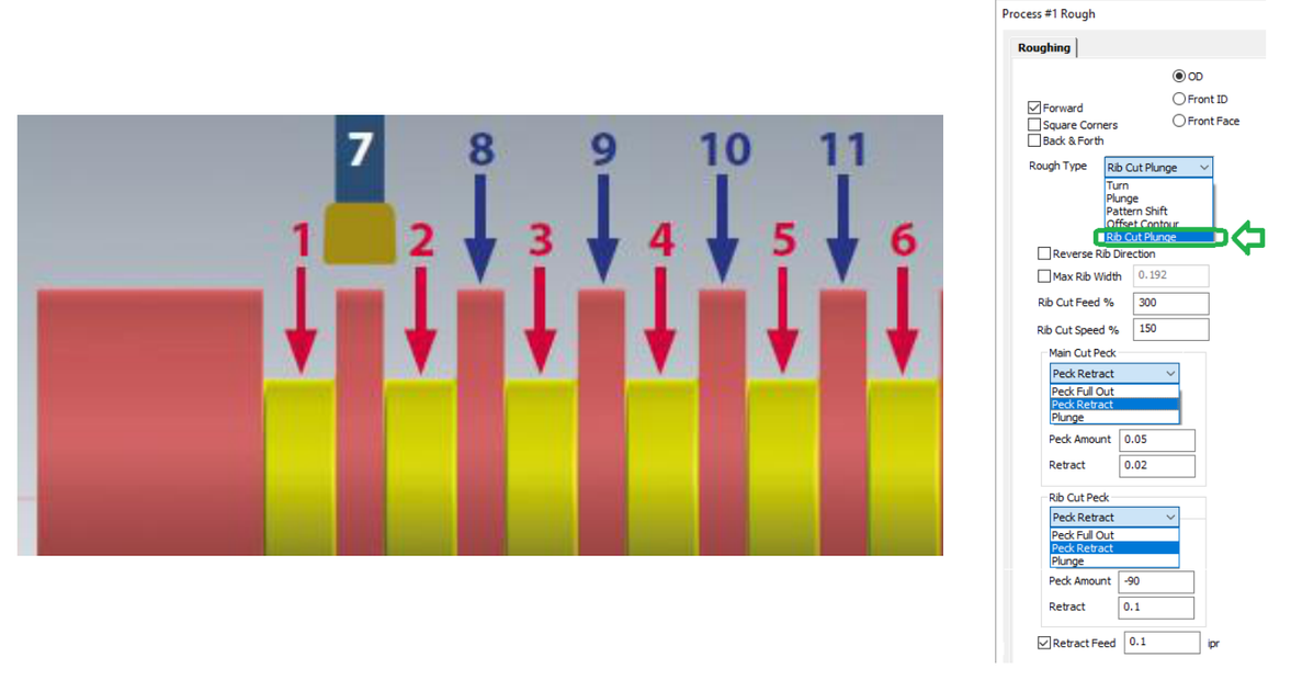
Figure 1 Rib Cut Plunge creates spaced cuts, then removes the remaining ribs
Source: What's New in GibbsCAM 2025, p. 16
Step 4 - Validate the Operation
1. Confirm that the preliminary cuts are spaced as intended and that the following pass removes the remaining ribs.
2. Run Op Simulation and inspect remaining stock, tool and holder clearance, peck motion, retracts, and rapid moves.
3. Post with the approved machine-specific post and review the output before controlled prove-out.
4. During prove-out, verify chip control, spindle load, dimensions, finish, cycle time, and insert wear.
Expected Result
• Rib Cut Plunge is available as the Rough Type in a supported Turning Rough process.
• The path creates separated preliminary plunges and then removes the remaining ribs.
• The approved tool and cutting data produce acceptable clearance, stock removal, load, chips, and finish.
Related Video

Best Practices
• Record the approved tool, material, Max Rib Width, cutting percentages, peck modes, and retract values.
• Change one Rib Cut control at a time and compare the result with a saved baseline.
• Compare Rib Cut with the established roughing strategy using cycle time, load, chips, finish, and insert wear.
• Revalidate after changing the tool, stock, profile, material, setup, machine, or post.
Troubleshooting
• Problem: Rib Cut Plunge is unavailable.
Cause
• The active process is not a supported Turning Rough process.
• The GibbsCAM build predates 2025 or the required Turning capability is unavailable.
Resolution
Confirm GibbsCAM 2025 and the Turning license, create a supported Turning Rough process, and reopen the Roughing tab.
• Problem: The path leaves excessive stock or irregular ribs.
Cause
• Max Rib Width is unsuitable for the tool width or part profile.
• The profile, stock allowance, direction, or tool geometry is incorrect.
Resolution
Verify the tool, profile, stock, allowance, direction, and Max Rib Width. Regenerate and inspect every preliminary plunge and rib-removal pass.
• Problem: The operation causes high load, deflection, or poor chip control.
Cause
• The cutting percentages or full-engagement pattern are unsuitable for the tool and material.
• Tool rigidity, machine power, peck motion, or chip evacuation is inadequate.
Resolution
Stop the test and return to approved tooling data. Correct the cutting values, rigidity, peck motion, or evacuation, then repeat simulation and controlled prove-out.
• Problem: Peck or retract motion is unsafe.
Cause
• The peck mode, amount, retract distance, or retract feed is incorrect.
• The stock, holder, fixture, or clearance definition is incomplete.
Resolution
Correct the peck and clearance data, regenerate the operation, and run complete simulation before posting again.
Related Articles
• Recommended Simulation Settings
• Create a Custom Stock Body for More Accurate Simulation
• How to Create a Pack and Go File
Explore More from CAMCO
Visit the CAMCO website to learn more about:
• Downloads and Helpful Resources
Keywords
GibbsCAM 2025, Turning, Turning Rough, Rib Cut Plunge, Max Rib Width, Rib Cut Feed, Rib Cut Speed, peck, tool deflection, chip control
Was this article helpful?
That’s Great!
Thank you for your feedback
Sorry! We couldn't be helpful
Thank you for your feedback
Feedback sent
We appreciate your effort and will try to fix the article