Summary
GibbsCAM 2025 expands 3-axis finishing with controls for machining flatlands after each slice, limiting paths by 3D contact-point boundaries, optimizing XY angles, and ordering passes by region or from outside to inside. It can also store contact-point normals for later compensation or tilting workflows.
Table of Contents
What Changed in GibbsCAM 2025
Important: These controls are strategy-specific. Confirm the installed GibbsCAM 2025 build, exact option labels, toolpath coverage, collision checks, and posted output before production use.
Before You Begin
• Use GibbsCAM 2025 with the applicable 3-Axis product and licensed strategy.
• Define the part, stock, tool, holder, containment, and fixtures accurately.
• Save a baseline path, simulation result, cycle time, and posted program.
• Identify the required flatland coverage, boundary behavior, cut angle, and region order before changing the operation.
Procedure
Step 1 - Control Flatlands and Containment
1. Use Machine Flatlands after Each Slice when supported and when flatlands must be cleared as the tool advances into deeper pockets.
2. Configure Dynamic Holder Collision when the strategy requires it for access and holder clearance.
3. Use the 3D contact-point boundary to limit finishing from the cut area defined on the actual part.
Step 2 - Optimize Cut Direction
1. For flatland or parallel-cut paths, enable the available Optimal XY Angle or Optimal machining angle in X,Y control.
2. Regenerate and confirm that each region uses a practical pass direction for material removal and surface quality.
3. Compare the calculated direction, path length, and tool engagement with the baseline.
Step 3 - Set Region and Pass Order
1. Use Ordering by Region when each region should be completed before the tool moves to the next region.
2. Use Outside-In ordering for flatland islands or regions when that sequence matches the machining plan.
3. Store contact-point normals only when the downstream compensation or tilting workflow requires them.
Step 4 - Review Other Strategy-Specific Controls
1. Where applicable, review smoothing, orthogonal lead extension, corner detection, inscribed-circle filtering, spiral undercut ordering, minimum shaft-length reporting, or smooth peg-loop controls.
2. Change only the control needed for the machining requirement and regenerate the operation.
3. Inspect coverage, direction changes, engagement, holder clearance, and any reported minimum shaft length.
Step 5 - Validate the Operation
1. Compare the new path with the saved baseline and confirm that every required region is machined once.
2. Run complete simulation with current stock, fixtures, tool, holder, and machine data.
3. Post the operation, review all cutting and transition motion, and complete controlled prove-out before release.
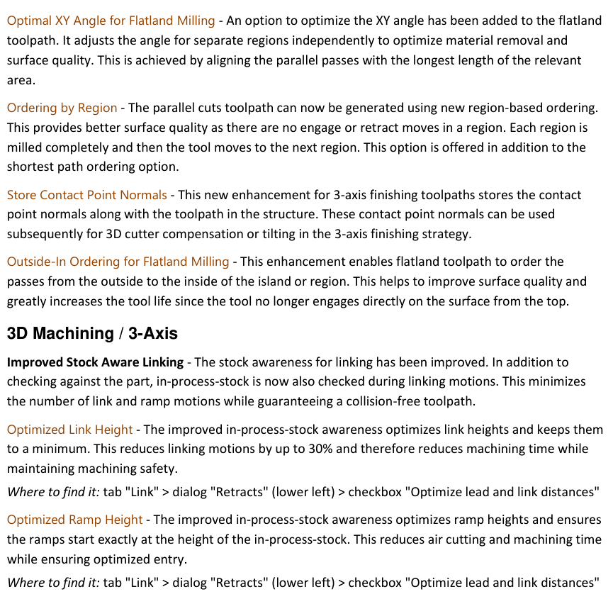
Figure 1 Representative 3-axis finishing and stock-aware linking changes
Source: What's New in GibbsCAM 2025, p. 32
Expected Result
• Flatlands and containment boundaries produce the intended coverage.
• Each region uses the approved cut direction and pass order.
• Simulation and posted output show complete machining without unintended cuts or collisions.
Best Practices
• Apply one finishing control at a time and retain the baseline operation.
• Define containment on the actual part and inspect all boundary transitions.
• Choose cut direction and order from the geometry and machining plan, not from the default alone.
• Revalidate after changes to geometry, tool, stock, containment, strategy, MDD, or post.
Troubleshooting
• Problem: A finishing control is missing.
Cause
• The selected strategy or build does not support the option.
• The required product, license, or advanced setting is not active.
Resolution
Confirm the GibbsCAM build, licensed products, selected strategy, and advanced settings. Use a supported cycle or contact CAMCO with the sample file and build details.
• Problem: Flatlands are not machined as expected.
Cause
• Machine Flatlands after Each Slice is disabled or unavailable.
• The flatland geometry, slice settings, or Dynamic Holder Collision configuration does not permit access.
Resolution
Verify the option, geometry, slices, tool reach, and collision settings. Regenerate from the baseline and inspect each slice in simulation.
• Problem: The contact-point boundary leaves or removes unintended path.
Cause
• The cut area, containment, tolerance, or tool definition is incorrect.
• The boundary is combined with an incompatible option or stale geometry selection.
Resolution
Redefine the cut area on the actual part, confirm tool and tolerance values, regenerate, and compare the complete boundary result with the baseline.
• Problem: Optimal angle or region ordering worsens the path.
Cause
• The automatic direction does not suit the local geometry or workholding.
• The selected order creates undesirable engagement, links, or surface marks.
Resolution
Return to the baseline, choose an explicit angle or alternate order, and compare coverage, engagement, links, and posted motion before accepting the change.
Related Articles
• Recommended Simulation Settings
• How to Create a Pack and Go File
Explore More from CAMCO
Visit the CAMCO website to learn more about:
• Downloads and Helpful Resources
Keywords
GibbsCAM 2025, 3-Axis finishing, Machine Flatlands after Each Slice, 3D contact point boundary, Optimal XY Angle, Ordering by Region, Outside-In, contact point normals, finishing controls
Was this article helpful?
That’s Great!
Thank you for your feedback
Sorry! We couldn't be helpful
Thank you for your feedback
Feedback sent
We appreciate your effort and will try to fix the article