Summary
GibbsCAM 2026 can create a separate Geodesic machining operation for the boundary of an area. The boundary pass can use its own stepover and tilting behavior, and the calculation is less sensitive to small changes in mesh input.
Table of Contents
What Changed in GibbsCAM 2026
Important: Improved robustness does not guarantee identical results after a mesh change. Recalculate and validate boundary quality, tool-axis motion, containment, and clearance whenever the input changes.
Before You Begin
• Use GibbsCAM 2026 with the required 5-Axis and supported Geodesic Machining capability.
• Define accurate drive surfaces or mesh, containment, stock, tool, holder, fixtures, and machine setup.
• Save a copy of the part and retain the current Geodesic operation as a baseline.
• Identify the required boundary finish, stepover, tilting behavior, and acceptance tolerance.
Procedure
Step 1 - Record the Baseline
1. Duplicate the affected Geodesic operation.
2. Record the mesh, containment, tool, stepover, tolerance, tilting, links, and estimated cycle time.
3. Calculate and simulate the baseline, then retain its boundary and surface result for comparison.
Step 2 - Create the Boundary Pass
1. Open the Geodesic operation and go to Surface paths > Containment > Advanced > Cut along containment.
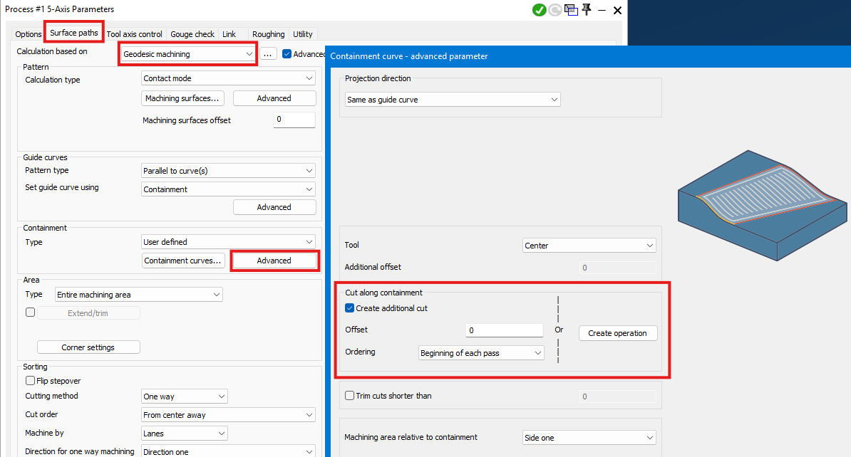
2. Create the boundary-pass operation.
3. Set its stepover, tilting behavior, and other required values independently from the main surface path.
4. Regenerate and inspect the boundary finish, tool-axis motion, containment, and collision clearance.
Step 3 - Compare Mesh Variations
1. Save the approved result before changing triangulation, mesh offset, or mesh patching.
Figure 1 Customize the boundary pass and compare stability after small mesh changes
Source: What's New in GibbsCAM 2026, p. 43
2. Apply the required mesh change and fully regenerate the operation.
3. Compare boundary location, pass order, tool-axis motion, links, and surface result with the saved baseline.
Step 4 - Validate the Output
1. Measure the boundary and finished surface against the job requirements.
2. Run Op Simulation and Machine Simulation with the production stock, fixtures, tool, and holder.
3. Post with the approved postprocessor and complete the shop's controlled prove-out.
Expected Result
• A separate boundary operation uses the selected stepover and tilting behavior.
• The boundary pass improves coverage and surface quality without creating unsafe motion.
• Small mesh changes have a reduced effect, and every revised result is still validated before release.
Best Practices
• Keep a calculated baseline before changing the mesh or boundary settings.
• Use conservative stepover and tilting values until the boundary result is verified.
• Compare measured surfaces and tool-axis motion instead of relying only on the displayed centerline.
• Revalidate after every triangulation, offset, patching, containment, or tool change.
Troubleshooting
• Problem: The boundary-pass operation is not created.
Cause
• Cut along containment is not enabled or the selected containment is invalid.
• The installed build or licensed strategy does not support the feature.
Resolution
Confirm the supported Geodesic operation, repair or select valid containment, enable Cut along containment, and recalculate.
• Problem: The boundary pass leaves stock or overlaps the surface path.
Cause
• The boundary stepover, allowance, tolerance, or containment is unsuitable.
• The tool or tilting behavior cannot maintain the required contact near the boundary.
Resolution
Verify containment and the complete tool assembly, then adjust boundary settings conservatively and recalculate before measuring the result.
• Problem: The tool axis moves unsafely near the boundary.
Cause
• Boundary tilting or collision settings are unsuitable for the local geometry.
• Fixture, holder, or machine-limit data is incomplete or inaccurate.
Resolution
Stop release, correct the complete setup, revise tilting and collision controls, and run full Op and Machine Simulation.
• Problem: A mesh change causes a larger toolpath difference than expected.
Cause
• Triangulation, offset, patching, containment, or tolerance changed beyond a small input deviation.
• The recalculated operation uses different tool, path, or tilting settings.
Resolution
Compare all inputs with the baseline, correct unintended differences, and recalculate. Treat the result as a new path and complete full validation.
Related Articles
• Recommended Simulation Settings
• How to Create a Pack and Go File
Explore More from CAMCO
Visit the CAMCO website to learn more about:
• Downloads and Helpful Resources
Keywords
GibbsCAM 2026, 5-Axis, Geodesic Machining, Multiple Boundary Passes, Cut along containment, boundary pass, stepover, tilting, mesh triangulation, mesh offset, mesh patching
Was this article helpful?
That’s Great!
Thank you for your feedback
Sorry! We couldn't be helpful
Thank you for your feedback
Feedback sent
We appreciate your effort and will try to fix the article