Summary
GibbsCAM 2025 adds Headstock Origin for supported Swiss-style machine definitions. The value is the distance between the front of the guide bushing and the headstock zero position. GibbsCAM uses it to position Simulation bodies on the headstock axis and to clarify the Swiss Dynamic Coordinate Definition setup.
Table of Contents
What Changed in GibbsCAM 2025
Important: Headstock Origin is machine-definition data, not a part work offset. Change it only in a controlled copy of a CAMCO-approved Swiss MDD with an authoritative machine measurement.
Before You Begin
• Use GibbsCAM 2025 and a CAMCO-approved Swiss-style MDD that supports a sliding headstock and guide bushing.
• Obtain the approved distance from the guide-bushing front to headstock zero, including units and sign convention.
• Confirm the matching simulation model, Dynamic Coordinate Definition, axis limits, and production post.
• Save a versioned backup of the MDD before making any change.
Procedure
Step 1 - Open a Controlled MDD Copy
1. Open Machine Manager with a versioned copy of the approved Swiss MDD.
2. Confirm the machine name, revision, units, Dynamic Coordinate Definition, and matching production post.
3. Record the current spindle and guide-bushing settings before editing them.
Step 2 - Select the Lathe Spindle Node
1. Select the P lathe-spindle node that represents the sliding headstock or main spindle.
2. Confirm that the selected part station and axis hierarchy match the physical machine.
3. Verify that Has Guide Bushing is enabled when required by the approved configuration.
Step 3 - Enter Headstock Origin
1. Enable Headstock Origin for the selected spindle node.
2. Enter the approved guide-bushing-to-headstock-zero distance using the MDD units and sign convention.
3. Save the machine definition under the approved name and revision process.
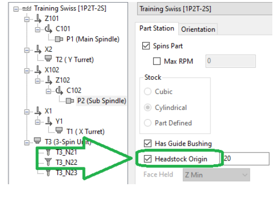
Figure 1 Headstock Origin locates the headstock zero from the guide-bushing front
Source: What's New in GibbsCAM 2025, p. 16
Step 4 - Validate the Swiss Setup
1. Open a representative Swiss part with the edited MDD and run Machine Simulation through the required headstock travel.
2. Confirm the positions of the stock, guide bushing, headstock, spindles, tools, turrets, subspindle, and fixtures.
3. Check Z-axis limits, zero-return behavior, bar advance, transfers, cutoffs, and inter-operation moves for collision or overtravel.
4. Review output from the matching approved post before controlled machine prove-out.
Expected Result
• Headstock Origin is available on the supported lathe-spindle node in the approved Swiss MDD.
• Simulation bodies are positioned correctly relative to the guide-bushing front and headstock zero.
• Machine Simulation, axis limits, posted output, and controlled prove-out agree with the physical machine.
Best Practices
• Use machine-builder documentation or a CAMCO-approved machine survey for the Headstock Origin value.
• Treat the MDD, simulation model, Dynamic Coordinate Definition, post, and machine parameters as one controlled configuration.
• Keep the original MDD and document every approved value, unit, sign, and revision.
• Repeat full simulation and posted-code review after changing machine geometry, limits, or coordinate conventions.
Troubleshooting
• Problem: Headstock Origin is unavailable.
Cause
• The selected node is not the supported P lathe-spindle node.
• The MDD does not support the Swiss setting or its guide-bushing data is incomplete.
Resolution
Select the correct spindle node and confirm that the approved Swiss MDD supports Has Guide Bushing and Headstock Origin. Do not retrofit an unsupported MDD without CAMCO review.
• Problem: Simulation bodies are shifted or move in the wrong direction.
Cause
• The Headstock Origin value, sign, or units are incorrect.
• The wrong spindle node, machine convention, or guide-bushing reference was used.
Resolution
Verify the measured distance, units, sign, selected node, stock origin, and coordinate convention. Correct the controlled MDD and rerun Machine Simulation.
• Problem: Headstock motion exceeds a limit or causes a collision.
Cause
• The axis limits, simulation-body origins, stock position, or clearance data do not match the machine.
• A transfer, cutoff, bar-advance, or inter-operation move uses the wrong reference.
Resolution
Stop release. Correct the MDD and part setup, then simulate the complete operating range and review posted motion before prove-out.
• Problem: Changing Headstock Origin does not affect the expected bodies.
Cause
• The edited MDD was not saved, reloaded, or assigned to the part.
• The value was entered on a spindle node that does not control the intended headstock bodies.
Resolution
Confirm the active MDD revision and controlling spindle node, reload the machine definition, and rerun Machine Simulation with the representative part.
Related Articles
• Recommended Simulation Settings
• How to Create a Pack and Go File
Explore More from CAMCO
Visit the CAMCO website to learn more about:
• Downloads and Helpful Resources
Keywords
GibbsCAM 2025, Swiss machine, sliding headstock, guide bushing, Headstock Origin, Machine Manager, MDD, Dynamic Coordinate Definition, DCD, simulation, Z-axis limits
Was this article helpful?
That’s Great!
Thank you for your feedback
Sorry! We couldn't be helpful
Thank you for your feedback
Feedback sent
We appreciate your effort and will try to fix the article