Summary
GibbsCAM 2025 adds Zig-Zag Threshold to Adaptive Roughing. Corner regions smaller than the entered multiple of tool diameter use one-way trochoidal connections, while longer contours retain zig-zag linking. This can improve corner engagement without applying the longer one-way pattern to the entire toolpath.
Table of Contents
What Changed in GibbsCAM 2025
Important: The release notes list Start Point Control without a description. It is excluded from this procedure until CAMCO validates its purpose, interface, and production-safe use.
Before You Begin
• Use GibbsCAM 2025 with a supported Adaptive Roughing strategy and the required license.
• Choose a test part that contains both small corner regions and longer toolpath contours.
• Define the tool diameter, stock, fixtures, holder, and machining limits accurately.
• Save the current path, simulation result, cycle time, and posted program as a baseline.
Procedure
Step 1 - Establish a Baseline
1. Regenerate the original Adaptive Roughing operation without changing its parameters.
2. Review the current corner links, engagement, total path length, cycle time, and warnings.
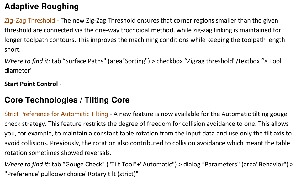
Figure 1 Compare adaptive corner linking and strict automatic tilt behavior
Source: What's New in GibbsCAM 2025, p. 34
3. Save the operation and simulation result for comparison.
Step 2 - Set the Zig-Zag Threshold
1. Open the Adaptive Roughing operation and go to Surface Paths > Sorting.
2. Enable Zigzag threshold and enter the approved value as a multiple of tool diameter.
3. Regenerate the operation before changing any other sorting or linking control.
Step 3 - Compare Link Behavior
1. Confirm that corner regions below the threshold use one-way trochoidal connections.
2. Confirm that longer contours retain zig-zag links.
3. Compare engagement, transition length, and total path length with the baseline. Adjust the threshold conservatively if the split does not match the machining plan.
Step 4 - Validate the Operation
1. Run complete simulation with current stock, fixtures, tool, holder, and machine data.
2. Inspect every corner transition for clearance, overload, abrupt direction changes, and remaining stock.
3. Post the operation, review all cutting and linking motion, and complete controlled prove-out before release.
Expected Result
• Small corner regions use one-way trochoidal links where intended.
• Longer contours retain the shorter zig-zag pattern.
• Simulation and posted output show safe motion without excessive path length.
Best Practices
• Test the threshold on geometry that contains both small and long contours.
• Change only the threshold while comparing results with the saved baseline.
• Use the smallest change that produces the required corner behavior.
• Revalidate after changes to geometry, tool diameter, stock, strategy, MDD, or post.
Troubleshooting
• Problem: Zig-Zag Threshold is unavailable.
Cause
• The active strategy or GibbsCAM build does not expose the control.
• The required product or license is not active.
Resolution
Confirm the installed build, licensed products, and selected Adaptive Roughing strategy. Use a supported configuration or send CAMCO the sample file and build details.
• Problem: All contours use the same link pattern.
Cause
• The entered tool-diameter multiple does not divide the selected geometry into small and long regions.
• Another sorting or linking setting governs the path.
Resolution
Restore the baseline, verify Surface Paths > Sorting, and test a conservative threshold on geometry with clearly different corner sizes. Regenerate after each change.
• Problem: Corner links become longer or less stable.
Cause
• The threshold assigns one-way links to too much of the path.
• The tool, tolerance, stock, or geometry does not suit the selected value.
Resolution
Reduce the threshold or return to the baseline. Confirm the tool and geometry, then compare engagement, direction changes, and path length before accepting the result.
• Problem: Simulation shows unexpected contact or remaining stock.
Cause
• Stock, fixture, tool, holder, or machine data is incomplete.
• The new links expose a clearance or engagement problem that was not visible in the baseline review.
Resolution
Stop release, correct the setup definitions, restore a safe threshold, and repeat complete simulation and posted-code review before prove-out.
Related Articles
• Recommended Simulation Settings
• How to Create a Pack and Go File
Explore More from CAMCO
Visit the CAMCO website to learn more about:
• Downloads and Helpful Resources
Keywords
GibbsCAM 2025, Adaptive Roughing, Zig-Zag Threshold, zig-zag linking, trochoidal linking, tool diameter, corner links, Surface Paths, Sorting
Was this article helpful?
That’s Great!
Thank you for your feedback
Sorry! We couldn't be helpful
Thank you for your feedback
Feedback sent
We appreciate your effort and will try to fix the article