Summary
GibbsCAM 2025 adds a Fade lead type, makes Automatic the default linker clearance behavior, and improves stock-aware linking. The linker can check in-process stock and optimize link and ramp heights to reduce unnecessary motion while maintaining clearance.
Table of Contents
What Changed in GibbsCAM 2025
Important: Automatic or optimized motion is not proof of machine safety. Simulate the complete setup, review posted motion and machine limits, and use the shop's controlled prove-out process.
Before You Begin
• Use GibbsCAM 2025 with the applicable 5-Axis or Advanced 3D product and license.
• Define the part, stock, in-process stock, tool, holder, fixtures, and machine components accurately.
• Save the current operation, simulation result, cycle time, and posted program as a baseline.
• Confirm the approved clearance policy and machine travel limits for the setup.
Procedure
Step 1 - Review Fade and Automatic Clearance
1. Open the applicable operation and review its lead and linker controls.
2. Where supported, test the Fade lead type and inspect how the tool approaches and leaves the machining surface.
3. Review the result when clearance is set to Automatic. Replace it with an approved explicit value if the generated motion is unsuitable.
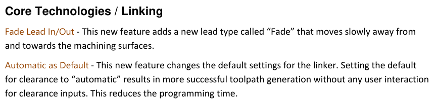
Figure 1 Fade linking and automatic-clearance behavior Source: What's New in GibbsCAM 2025, p. 31
Step 2 - Optimize Link and Ramp Heights
1. Open Link, then Retracts.
2. Enable Optimize lead and link distances for a supported operation.
3. Regenerate and compare link height, ramp height, air cutting, and total path length with the baseline.
Step 3 - Include In-Process Stock in Collision Checks
1. Confirm that the in-process stock is current before calculating the path.
2. Where applicable, open Dynamic Holder Collision and enable Check with in-process stock.
3. Regenerate and inspect every link, ramp, lead, and retract near stock and fixturing.
Step 4 - Validate Motion and Output
1. Run complete simulation with stock, fixtures, tool, holder, and machine components displayed as applicable.
2. Compare cycle time and transition count with the baseline without accepting reduced clearance.
3. Post the operation, review all non-cutting motion, and complete controlled prove-out before production release.
Expected Result
• Fade or automatic-clearance motion approaches and leaves the surface as intended.
• Link and ramp heights follow the current in-process stock without unnecessary air cutting.
• Simulation and posted output remain clear of stock, fixtures, holders, and machine components.
Best Practices
• Update in-process stock before trusting optimized link or ramp heights.
• Change one linking control at a time and compare with a saved baseline.
• Use automatic values only after complete simulation confirms the result.
• Revalidate after any geometry, stock, tool, holder, fixture, MDD, strategy, or post change.
Troubleshooting
• Problem: Fade is unavailable.
Cause
• The active strategy or build does not support the lead type.
• The required product or license is not active.
Resolution
Confirm the operation, GibbsCAM build, products, and licenses. Use a supported strategy or provide CAMCO with the sample file and build details.
• Problem: Automatic clearance creates unexpected motion.
Cause
• The automatic result does not suit the local geometry.
• Stock, fixtures, tool, holder, or machine data is incomplete.
Resolution
Restore the baseline, complete the setup definitions, and use an approved explicit clearance. Regenerate and repeat complete simulation.
• Problem: Optimized links or ramps approach stock.
Cause
• The in-process stock is stale or incomplete.
• Optimize lead and link distances is unsuitable for the current operation or setup.
Resolution
Stop release. Update the stock state, verify all setup geometry, increase clearance or restore the baseline, and repeat simulation and posted-code review.
• Problem: The new settings add motion or increase cycle time.
Cause
• Avoidance checks require extra transitions around the current stock or fixtures.
• The selected lead or clearance combination is more conservative than the baseline.
Resolution
Compare the path segment by segment, keep the safety requirement unchanged, and use the simplest approved combination that passes complete validation.
Related Articles
• Create a Custom Stock Body for More Accurate Simulation
• Recommended Simulation Settings
• How to Create a Pack and Go File
Explore More from CAMCO
Visit the CAMCO website to learn more about:
• Downloads and Helpful Resources
Keywords
GibbsCAM 2025, 5-Axis linking, Fade lead, automatic clearance, stock-aware linking, in-process stock, optimized link height, optimized ramp height, Dynamic Holder Collision, DHC
Was this article helpful?
That’s Great!
Thank you for your feedback
Sorry! We couldn't be helpful
Thank you for your feedback
Feedback sent
We appreciate your effort and will try to fix the article