Summary
GibbsCAM 2026 adds Plane, Cylinder, Sphere, and Surface clearance areas. It also improves automatic cylindrical and spherical clearance, supports user-defined clearance surfaces, and adds a Virtual Fixture Plane for Sphere Clearance.
Table of Contents
What Changed in GibbsCAM 2026
Important: A shorter retract is acceptable only when the full tool assembly remains clear of the part, stock, fixtures, and machine.
Before You Begin
• Use GibbsCAM 2026 with a supported Multi-Axis operation.
• Define accurate stock, part, tools, holders, fixtures, and machine components.
• Duplicate the operation and retain its retracts, links, simulation, and cycle time as a baseline.
• Identify a clearance shape that covers the complete setup envelope.
Procedure
Step 1 - Choose a Clearance Type
1. Open Link > Clearance area > Clearance area dialog.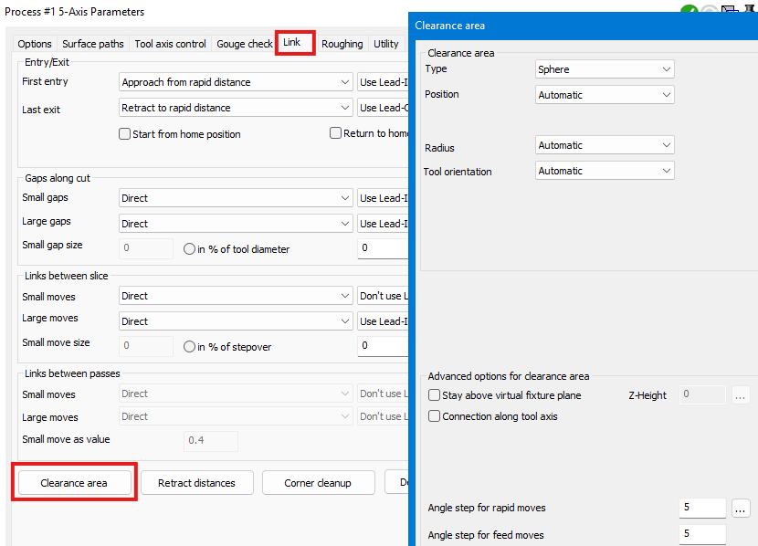
2. Choose Plane, Cylinder, Sphere, Surface, or Automatic as supported by the operation.
3. Use the simplest type that covers the complete setup envelope.
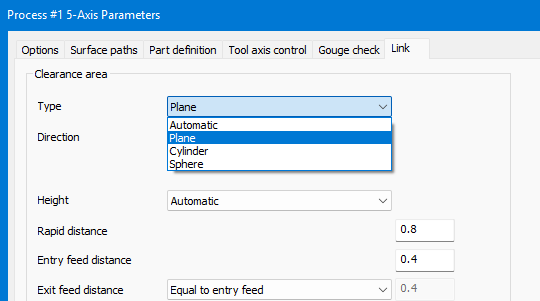
Figure 1 Choose a clearance type that matches the setup envelope
Source: What's New in GibbsCAM 2026, p. 41
Step 2 - Define the Area
1. For Plane, set height and normal direction.
2. For Cylinder, set radius and direction; for Sphere, set radius and position.
3. For Surface or a user-defined area, select only surfaces that form a continuous safe envelope.
4. Regenerate and inspect every retract and link.
Step 3 - Use Automatic Clearance
1. Use Automatic, or set supported Cylinder or Sphere position and radius options to automatic.
2. Regenerate and compare link length, clearance, and cycle time with the baseline.
3. Keep the longer result when it is required for safe clearance.
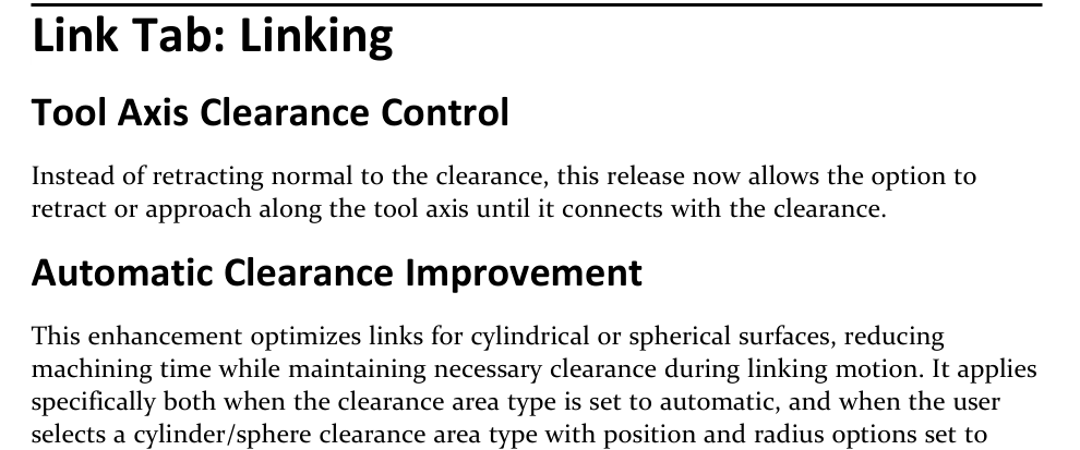
Figure 2 Automatic clearance can shorten cylindrical or spherical links
Source: What's New in GibbsCAM 2026, p. 45
Step 4 - Protect Sphere Clearance with a Virtual Plane
1. Use Sphere Clearance; Virtual Fixture Plane is limited to this clearance type.
2. Open Link > Retracts, enable Virtual Fixture Plane, and enter the protective height.
3. Regenerate and confirm that links stay on the safe side of the plane.
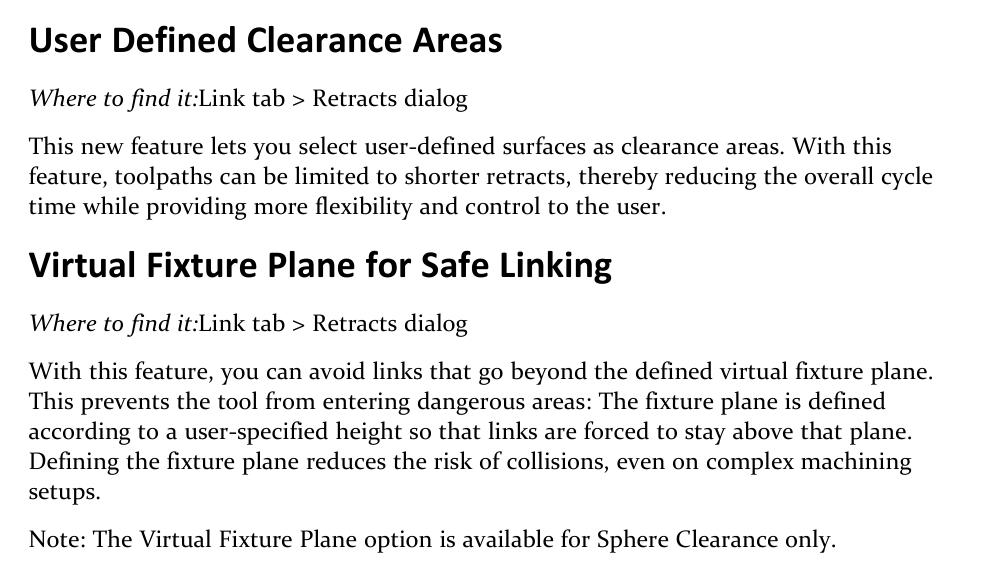
Figure 3 Use selected surfaces or a Sphere Clearance fixture plane for complex setups
Source: What's New in GibbsCAM 2026, p. 45
Step 5 - Validate the Result
1. Run Op Simulation and Machine Simulation with the full tool assembly and setup visible.
2. Review every retract, link, near-miss, collision, and machine limit.
3. Post with the approved postprocessor and complete controlled prove-out.
Expected Result
• The clearance area covers the complete setup envelope.
• Automatic or user-defined areas shorten links only where motion remains safe.
• Virtual Fixture Plane keeps Sphere Clearance links above the protective height.
Best Practices
• Choose clearance from the real setup, not only the part shape.
• Change one clearance control at a time.
• Use conservative offsets and the complete tool assembly.
• Revalidate after any setup, tilt, tool, or fixture change.
Troubleshooting
• Problem: Retracts or links intersect the setup.
Cause
• The clearance area does not cover the complete envelope.
• Height, radius, position, direction, surfaces, or setup models are incorrect.
Resolution
Stop before machining, correct the clearance and setup definitions, regenerate, and simulate every link.
• Problem: Automatic clearance does not shorten the links.
Cause
• The strategy or build does not expose the improved behavior.
• Automatic position or radius is not active, or constraints require the longer route.
Resolution
Confirm support and automatic settings, then keep the longer result when it is required for safety.
• Problem: A user-defined surface is ignored or produces erratic motion.
Cause
• The wrong surfaces were selected or they do not form a usable envelope.
• Orientation, gaps, stock, containment, or machine limits conflict with the links.
Resolution
Select a simple continuous surface set, verify orientation, regenerate, and inspect from multiple views.
• Problem: Virtual Fixture Plane is unavailable or crossed.
Cause
• The active type is not Sphere Clearance.
• The plane height or link settings do not protect the intended region.
Resolution
Select Sphere Clearance, enable Virtual Fixture Plane, correct the height, and verify every crossing.
Related Articles
• Recommended Simulation Settings
• How to Create a Pack and Go File
Explore More from CAMCO
Visit the CAMCO website to learn more about:
• Downloads and Helpful Resources
Keywords
GibbsCAM 2026, Multi-Axis, clearance area, Plane Clearance, Cylinder Clearance, Sphere Clearance, Surface Clearance, automatic clearance, user-defined clearance, Virtual Fixture Plane, retract, link
Was this article helpful?
That’s Great!
Thank you for your feedback
Sorry! We couldn't be helpful
Thank you for your feedback
Feedback sent
We appreciate your effort and will try to fix the article