Summary
GibbsCAM 2024 adds Auto, At center, At radius, and At front choices to Run tool for the Project Curves strategy. The selected mode controls how the tool is positioned relative to the projected curves and can change tool orientation and clearance along the path.
Table of Contents
What Changed in GibbsCAM 2024
Important: The four choices can produce different tool-axis motion. Recalculate and review the complete path after changing Run tool.
Before You Begin
• Use GibbsCAM 2024 with the approved machine definition, post, and licensed surface-machining options.
• Inspect the machining surfaces and projected curves for gaps, overlaps, or unintended branches.
• Confirm the physical tool, holder, stickout, and required clearances.
• Save a working copy and retain a baseline toolpath and simulation result.
Procedure
Step 1 - Select Project Curves
1. Create or edit the operation and set Calculation based on to Surfaces.
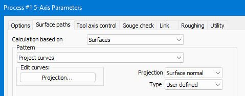
2. Select Project Curves and confirm the intended curves and machining surfaces.
3. Verify the cutting tool and the active machine configuration before calculating the path.
Step 2 - Choose the Run Tool Mode
1. Open Tool axis control.
2. From Run tool, choose Auto, At center, At radius, or At front for the current test.
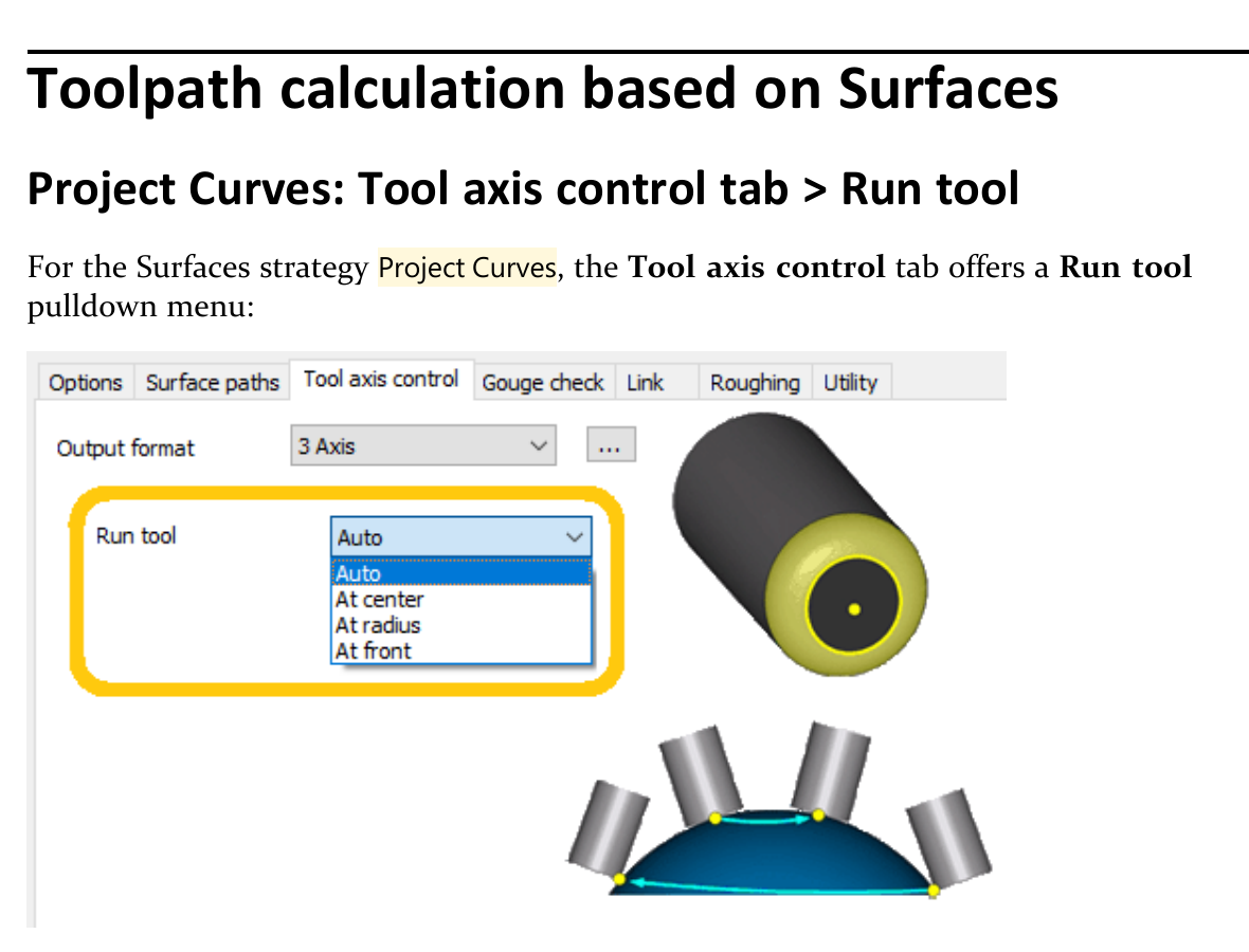
Figure 1 Project Curves adds four Run tool choices Source: What's New in GibbsCAM 2024, p. 26
3. Change only this setting when comparing the four modes against the saved baseline.
Step 3 - Compare the Tool Axis Motion
1. Recalculate the operation and display the toolpath.
2. Review the tool position and orientation along straight segments, corners, and changes in surface shape.
3. Check holder clearance, machine reach, rotary travel, and abrupt tool-axis changes.
Step 4 - Validate the Selected Mode
1. Run Op Simulation and Machine Simulation with the complete tool and holder assembly.
2. Compare the result with the baseline and confirm that the selected mode follows the intended projected curves.
3. Review the posted rotary motion and complete a controlled prove-out before production use.
Expected Result
• Run tool displays all four GibbsCAM 2024 choices for Project Curves.
• The calculated path uses the selected tool-position mode consistently along the projected curves.
• Simulation and posted output show reachable motion with the required clearance.
Best Practices
• Compare one Run tool mode at a time against the same geometry and tool assembly.
• Repair surface or curve defects before adjusting tool-axis controls.
• Review rotary travel and holder clearance across the entire path, not only the cutting region shown in the workspace.
• Keep the validated mode with the operation and setup documentation.
Troubleshooting
• Problem: The Run tool menu is unavailable.
Cause
• Calculation based on is not set to Surfaces.
• The strategy, GibbsCAM version, or installed option does not support the control.
Resolution
Confirm GibbsCAM 2024, the required license, Surfaces as the calculation basis, and Project Curves as the strategy. Reopen Tool axis control.
• Problem: The tool does not run in the expected position.
Cause
• A different Run tool mode is selected.
• The projected curves or machining surfaces do not match the intended geometry.
Resolution
Confirm the selected mode and geometry, recalculate, and compare with the baseline. Test the remaining modes before changing other tool-axis settings.
• Problem: The tool axis changes abruptly or exceeds machine travel.
Cause
• The selected mode creates an orientation the machine cannot reach smoothly.
• The machine definition, rotary limits, or tool-axis constraints do not match the setup.
Resolution
Stop release. Verify the machine definition and limits, test another approved mode, and simulate the complete operation before posting again.
• Problem: Holder interference remains after the path is recalculated.
Cause
• The tool assembly or stickout is incomplete.
• The selected Run tool mode does not provide enough clearance for the geometry.
Resolution
Correct the tool and holder definition, verify protected geometry and clearances, then compare supported Run tool modes and simulate the full path.
Related Articles
• Recommended Simulation Settings
• How to Create a Pack and Go File
Explore More from CAMCO
Visit the CAMCO website to learn more about:
• Downloads and Helpful Resources
Keywords
GibbsCAM 2024, 5-Axis, Surfaces, Project Curves, Run tool, Auto, At center, At radius, At front, Tool axis control
Was this article helpful?
That’s Great!
Thank you for your feedback
Sorry! We couldn't be helpful
Thank you for your feedback
Feedback sent
We appreciate your effort and will try to fix the article