Summary
GibbsCAM 2024 adds Wireframe 2-Axis Contouring for direct curve-following toolpaths at a specified Z level. The operation can map toolpath contours to drive-curve features so process information remains associated with the intended contour.
Table of Contents
What Changed in GibbsCAM 2024
Important: Editing or resequencing curves after mapping can change which process information belongs to each contour. Review the mapping after geometry changes.
Before You Begin
• Use GibbsCAM 2024 with the required Wireframe machining option.
• Repair gaps, overlaps, duplicates, branches, and unintended direction changes in the drive curves.
• Confirm the cutting side, offset, Z level, tool, stock, and clearance planes.
• Save a working copy and retain a baseline toolpath when updating an existing operation.
Procedure
Step 1 - Select the Drive Curves
1. Inspect and sequence the wireframe curves that define the required contours.
2. Confirm curve direction and remove duplicate or unintended branches.
3. Select only the curves that should produce machining motion.
Step 2 - Create the Contouring Operation
1. Set Calculation based on to Wireframe and select 2-Axis Contouring.
2. Choose the drive curves, cutting side, and offset.
3. Enter the required Z level or height data and calculate the operation.
Step 3 - Map Toolpaths to Drive Curves
1. Open the Utility tab when process information must stay associated with individual contours.
2. Enable Map toolpath to drive curves.
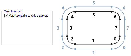
3. Regenerate and verify each feature-to-contour association.
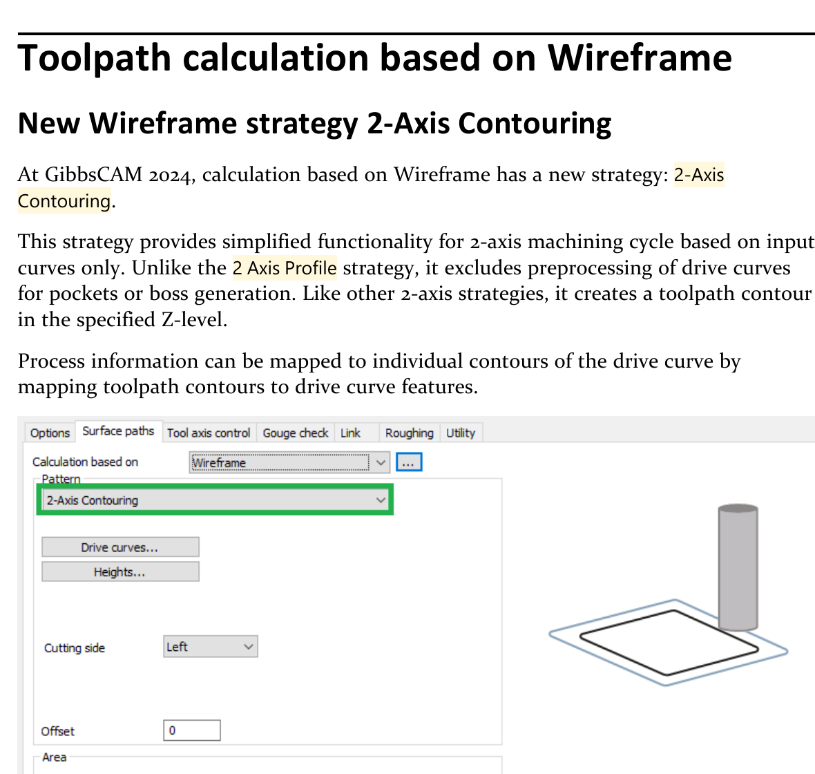
Figure 1 2-Axis Contouring follows input curves without pocket or boss preprocessing Source: What's New in GibbsCAM 2024, p. 28
Step 4 - Validate the Contours
1. Review contour order, start points, cutting side, offsets, and Z levels.
2. Run Op Simulation and Machine Simulation with stock, fixtures, and the complete tool assembly visible.
3. Compare the result with the baseline and review the posted motion before prove-out.
Expected Result
• Each selected curve produces the intended contour at the specified Z level.
• Cutting side, offset, order, and start points match the programmed geometry.
• Mapped process information remains associated with the intended drive-curve feature.
Best Practices
• Repair and sequence curves before creating the operation.
• Use 2-Axis Contouring for direct curve-following and 2-Axis Profile when pocket or boss preprocessing is required.
• Review mapping whenever curves are edited, replaced, or reordered.
• Keep one validated operation as a baseline when comparing curve or offset changes.
Troubleshooting
• Problem: The 2-Axis Contouring strategy is unavailable.
Cause
• Calculation based on is not set to Wireframe.
• The installed GibbsCAM version or options do not include the strategy.
Resolution
Confirm GibbsCAM 2024, the required option, and Wireframe as the calculation basis. Reopen the strategy list.
• Problem: The operation does not produce the expected contours.
Cause
• Drive curves contain gaps, overlaps, duplicates, branches, or direction changes.
• The job requires 2-Axis Profile preprocessing instead of direct contouring.
Resolution
Repair and resequence the curves, regenerate, and use 2-Axis Profile when pocket or boss preprocessing is required.
• Problem: The path is on the wrong side or Z level.
Cause
• The cutting side, offset, or Z level is incorrect.
• Curve direction differs from the expected sequence.
Resolution
Verify curve direction, cutting side, offset, and Z data, then recalculate and inspect every contour.
• Problem: Process information maps to the wrong contour.
Cause
• Curve selection or feature order changed after mapping.
• Curves were edited after the operation was created or mapping is disabled.
Resolution
Enable Map toolpath to drive curves, reselect the intended curves, regenerate, and review every feature-to-contour association.
Related Articles
• How to Machine Open Shapes in GibbsCAM
• Recommended Simulation Settings
• How to Create a Pack and Go File
Explore More from CAMCO
Visit the CAMCO website to learn more about:
• Downloads and Helpful Resources
Keywords
GibbsCAM 2024, Wireframe, 2-Axis Contouring, drive curve, cutting side, offset, Z level, Map toolpath to drive curves, contour mapping
Was this article helpful?
That’s Great!
Thank you for your feedback
Sorry! We couldn't be helpful
Thank you for your feedback
Feedback sent
We appreciate your effort and will try to fix the article